
Quick Answer: Plan ATE load board testing as separate bare-board, assembled-interface and tester bring-up checks before releasing a load board PCB. Match each result to the board revision and tested path, then compare reference devices across sites when a failure appears. Keep unexplained intermittent results open until the test owner approves the investigation and repeat checks.
A load board PCB connects automated test equipment (ATE) to a packaged device under test (DUT). A failing measurement can come from the device, its socket, the assembled board or the tester setup. The ATE load board testing checks below help you decide which hardware to hold and what evidence allows it to move forward.
What must load board PCB acceptance prove?
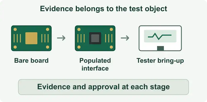
Acceptance must establish that the delivered hardware matches the released design and has passed the checks assigned to its current build stage. A fabricated PCB, a populated interface and a board operating on the tester are different test objects. Each needs evidence before the next stage begins.
Bare-board electrical testing checks the fabricated interconnections against the released netlist under the specified test conditions. Populated-interface checks add the components and hardware fitted during assembly. Tester bring-up introduces the tester configuration, program and reference devices. Device qualification requires its own plan.
Here, a site is one DUT test position, its socket provides the device contacts, a path is the route being measured, and a channel is the tester resource connected to it. This article covers packaged-device load boards; wafer probe cards have a different contact interface.
Which evidence belongs to the bare fabricated board?
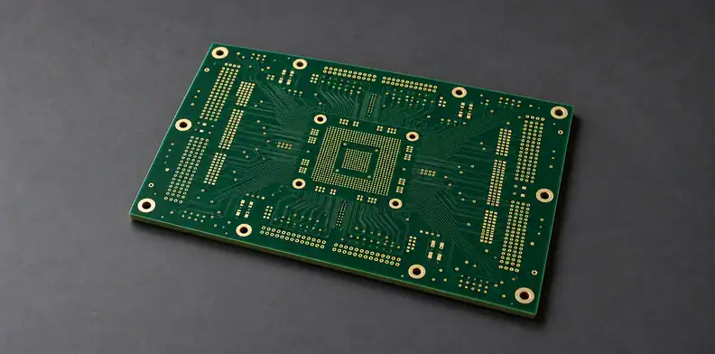
The bare-board package should connect the electrical-test result and drawing-specified fabrication records to the released data revision and shipped lot. Resolve test exceptions before assembly obscures access to the board. Review any approved deviations beside the original requirement so that receiving inspection can identify the construction being accepted.
An impedance coupon report describes the representative structure built on the coupon. It leaves socket transitions, relays and the assembled DUT path for later verification. Use the existing impedance test report guide for the detailed report review. The ATE PCB manufacturing page covers fabrication scope and the drawings needed for a manufacturing inquiry.
What changes once the interface is assembled?
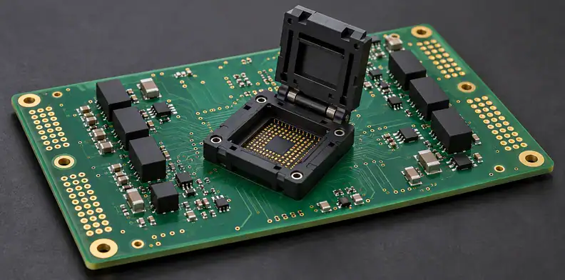
Assembly adds soldered connections, components, connectors and any fitted sockets or mechanical hardware to the test object. A correct bare-board netlist result leaves those additions unchecked. Agree which populated checks will verify the delivered assembly, who performs them and how exceptions will be recorded before releasing the build.
Equipment manufacturer SPEA describes load-board defect types such as socket-to-PCB connections, contact faults, weak relays and leakage. These are reasons to define assembled-board coverage rather than infer it from a fabrication test certificate.
QueenEMS has AOI, X-ray, flying-probe, ICT and functional-test methods available, with coverage agreed per project. A particular leakage, RF or socket diagnostic program needs separate confirmation. Socket or stiffener fitting is included only when quoted; tester correlation remains with your test engineering team.
Who owns each stage, and what triggers a hold?
Assign an evidence provider, a buyer-side approver and a hold condition to each stage before moving the hardware forward. The provider supplies the records; the approver decides whether they meet the released requirement. An open item needs a documented disposition and owner, including when limited engineering work may proceed.
Use this suggested release map to record those decisions:
| Stage and evidence | Owner and hold condition |
|---|---|
| Bare board: revision match, netlist result and specified fabrication reports. | Fabricator provides; buyer verifies. Hold for a mismatch, unresolved test exception or missing required report. |
| Populated interface: assembly inspection and agreed electrical checks. | Assembler provides; buyer verifies. Hold for a failed or omitted check, or unrecorded rework. |
| Tester bring-up: baseline by site using reference devices. | Customer test engineering approves. Hold for unexplained site differences or intermittent behavior. |
How should the first tester bring-up be controlled?
Start controlled bring-up after the fabrication and assembly evidence has been accepted, or after the test owner has approved specific restrictions for open items. Freeze the board configuration, tester setup and program revision. Establish reference-device results at each site before using those results to judge production devices.
Choose reference devices with an established identity and expected behavior under the intended test conditions. A device that passed once on the suspect board provides a weak reference. Record how the reference was established, and use the test owner’s procedure for powering, loading and moving devices.
Capture the same test, units, limits, operating conditions and site mapping for each comparison. Keep the device identity attached to its result as it moves. For power-sensitive measurements, record the configured rail and measurement point; for relay-switched paths, record the selected route. Otherwise, apparently equivalent sites may be exercising different conditions.
Set the repeat count and acceptable site variation in the approved bring-up plan. These come from the measurement task and test requirements. Preserve the baseline with the board serial number, hardware revision and program version so that a later repair can be compared with the correct configuration.
How do you tell a site fault from a bad DUT?
Track whether the symptom follows an identified device, remains at a test site or affects every site under controlled conditions. Change one variable at a time and keep the original failure record. These comparisons narrow the investigation; the test owner still decides whether the evidence supports a device, interface or setup fault.
The following is a suggested diagnostic sequence for a multisite interface. Follow the approved power-down and handling procedure before moving devices or touching contacts.
- Record the failing test, device identity, site, selected path and measured result. Preserve the setup and original log before repeating anything.
- Repeat with the same configuration as the test plan allows. Record intermittent behavior, including passes, against the original failure.
- Compare a suitable reference device at the suspect site and the suspect device at a previously verified site, where the hardware and test plan permit. Keep the program, settings and connection state controlled.
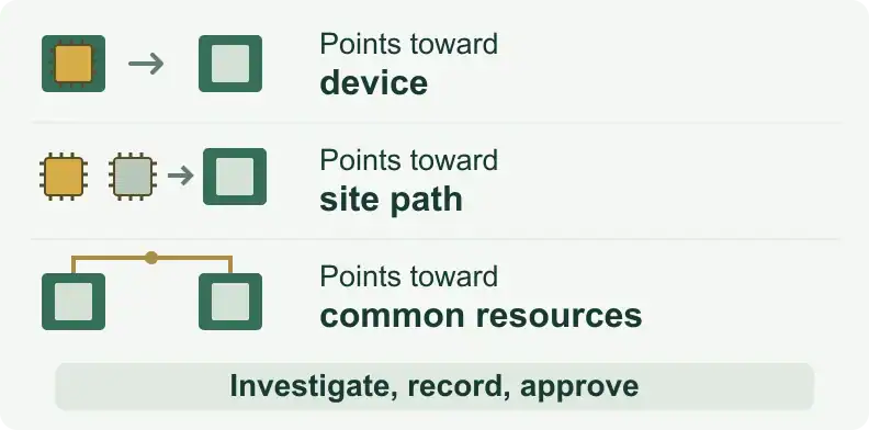
- Review the pattern. A symptom following the device points toward a device-related cause, but it does not clear the original site by itself: a device overstressed at a faulty site can then fail everywhere. A symptom staying at one site across reference devices points toward that site’s contact or signal path. A failure across sites calls for investigation of common resources, setup and board-wide paths.
- Hold the affected hardware while the cause remains unresolved. Inspect socket condition and seating, then investigate the connections, selected relay route and components in that path. Escalate common failures to the test owner.
For example, a failure confined to one site after exchanging suitable reference devices justifies investigating that site before treating the devices as failures. It does not identify which contact or component failed. If the symptom changes after reseating, record that action and verify repeatability before deciding the repair is complete.
A retest pass with no explained change should remain recorded as “not reproduced.” The test owner defines what further evidence closes it. Disabling a site for continued testing also needs approval of the revised site map, program configuration and coverage.
What should a site diagnostic and repair record contain?
A useful record lets another engineer repeat the comparison, identify every intervention and see why the hardware returned to service. Tie results to the physical board, site, device and configuration. Keep the initial failure, investigation and closure together so that a later passing result cannot erase the earlier symptom.
Use one record per investigated site or path. Link related records when a common resource affects several sites. This suggested form can sit beside the test log:
| Record item | What to capture |
|---|---|
| Identity | Board serial and revision; site and socket position; tester channel and net or path where known. |
| Configuration and failure | Tester and program versions; test name, units, limits, conditions, device IDs and original result. |
| Controlled comparison | Device-to-site movements, unchanged settings, repeat results and whether the symptom followed the DUT, stayed at a site or affected all sites. |
| Investigation and action | Contact inspection, measurements, operator and instrument; cleaning, replacement, rework or no intervention. |
| Closure | Checks repeated, results and remaining restrictions; disposition, approver and date. |
Choose the recheck scope from the intervention. Replacing a socket contact calls for verification of the affected contact path and the applicable assembled-interface checks. Reworking a component can affect neighboring connections. A hardware or program change may require a new per-site baseline; keep the earlier baseline identified rather than silently replacing it.
Close the record only when the required checks and any restrictions have an approved disposition. Purchasing can then distinguish a fabrication acceptance, an assembly release and a test-engineering decision to return a site to use.
Frequently Asked Questions
Is a passing bare-board electrical test enough to release a load board?
No. It covers the fabricated board under its specified test conditions. Assembly introduces additional connections and parts, followed by a separate bring-up decision on the tester.
Does an impedance coupon report prove each site’s signal path?
No. It measures a representative structure. The populated route includes interfaces and parts that need the verification assigned to that path.
Who should own tester correlation?
Your test engineering team should own the reference devices, comparison conditions, limits and release decision. Put any supplier-provided portion in the agreed scope rather than assuming it accompanies PCB fabrication.
What files should I send for a load board PCB quote?
Gerber and drill data, the stackup and fabrication drawing define the bare-board request. Include a BOM for requested assembly and state which inspection or test evidence must accompany delivery.
Send your released files for a quote and free DFM review.
Send Gerber, drill data, stackup and drawings for a PCB quote. Specify quantities and the bare-board acceptance records your load-board order needs.
For assembly, add the BOM and assembly data. Agree inspection and board checks; tester bring-up and correlation stay with your test team.