
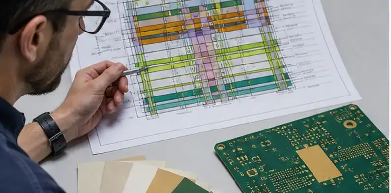
Quick Answer: A high frequency hybrid PCB stackup is ready for RFQ only when the RF layers, reference planes, material callouts, dielectric thicknesses, and impedance evidence are defined before CAM review. The buyer should not ask only whether the factory can mix Rogers or PTFE with FR4; the safer question is which layers carry RF energy, which layers are structural or digital, and what manufacturing evidence will prove the stackup was built as released.
Key takeaways
For a broader comparison of laminate families, electrical properties, processing limits, and sourcing choices, see our PCB materials guide.
- Use hybrid construction to place low-loss material only where RF performance needs it.
- Do not release the RFQ without a stackup drawing that separates RF, digital, power, and reference layers.
- Material compatibility, CTE, resin behavior, drilling, and desmear are manufacturing questions, not only design choices.
- Ask for impedance, cross-section, and stackup signoff evidence before the order becomes irreversible.
A high frequency hybrid PCB stackup usually appears when an RF section needs low-loss material, but the whole board does not justify premium laminate on every layer. That is common in antenna modules, RF front ends, radar subassemblies, radio units, and mixed RF/digital control boards.
The buying risk is that the word hybrid sounds simple. In production, the stackup mixes electrical intent with lamination behavior, drill preparation, dimensional movement, and inspection evidence. A supplier may be comfortable with one Rogers and FR4 construction but cautious about another PTFE and FR4 combination.
This page is separate from a general Rogers material article. It is written for the buyer or engineer preparing the RFQ package and deciding what QueenEMS or another fabricator must confirm before manufacturing starts.
Table of Contents
- Define what hybrid means for this board
- Place RF layers where the signal can stay controlled
- Check material compatibility before CAM promises a build
- Ask how lamination and drilling will be controlled
- Keep cost savings visible but not dominant
- Release a quote-ready stackup package
- Review surface finish, solder mask, and copper roughness together
- Set the first-lot review before repeat orders
- Use RFQ wording that forces a comparable supplier answer
Define what hybrid means for this board
For an RFQ, hybrid should mean a specific layer construction, not a marketing label. State which layers use Rogers, PTFE, hydrocarbon ceramic, or another low-loss laminate, and which layers use FR4 or high-Tg FR4 for power, control, shielding, or mechanical support.
The useful first check is whether the RF path is actually isolated on the low-loss layers. If the controlled RF trace moves through FR4 transitions, long vias, or poorly referenced layer changes, the material saving can be cancelled by signal discontinuity.
A purchasing record should name the performance reason for the hybrid build: lower RF loss, phase stability, antenna feed consistency, cost reduction versus all-premium material, or integration of RF and digital circuits on one PCB.
| Stackup choice | What it usually means | RFQ check |
|---|---|---|
| Low-loss material only on RF layers | Cost is controlled while RF path stays protected | Are the RF traces and reference planes fully on those layers? |
| Low-loss core with FR4 buildup | Mechanical and digital layers stay lower cost | Is the lamination interface approved? |
| All-premium RF section | Performance margin is prioritized | Is the added material cost justified by the requirement? |
RFQ signal: Treat hybrid as a released stackup decision only after the low-loss layers and non-critical FR4 layers are named in the drawing.
Place RF layers where the signal can stay controlled
Most high frequency hybrid PCB stackup decisions become safer when the RF layers have adjacent reference planes and short, controlled transitions. Outer-layer RF routing can simplify launch tuning and inspection, while inner RF routing may protect traces but increases the burden on dielectric control and via transitions.
The stackup review should ask where the antenna feeds, filters, couplers, amplifiers, and phase-sensitive paths actually sit. A hybrid build is not automatically good because Rogers or PTFE appears somewhere in the material list.
| RF placement choice | Works when | Buyer should confirm |
|---|---|---|
| Outer low-loss layer | RF traces and launches need inspection or tuning | Surface finish, mask clearance, copper roughness, plane spacing |
| Inner stripline low-loss layer | RF routing needs shielding | Dielectric thickness, reference planes, via transitions |
| Low-loss core only under RF zone | Only one region is frequency-critical | Registration and fabrication feasibility |
| All low-loss board | Nearly every layer carries critical RF | Cost and lead-time impact |
For broader RF capability context, connect this decision to the QueenEMS RF PCB manufacturer page. This article focuses on the pre-quote stackup evidence that prevents RFQ ambiguity.
Layer rule: Put premium material where the RF path can use it continuously, not where it merely looks impressive in the BOM.
Check material compatibility before CAM promises a build
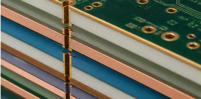
Material compatibility is the part buyers often underestimate. Low-loss laminates and FR4 can differ in CTE, cure behavior, resin flow, moisture behavior, drill response, and dimensional movement. Those differences affect registration, plating consistency, bow and twist, and delamination risk.
Rogers states that RO4350B provides low loss while using processing methods similar to standard epoxy/glass, with controlled Dk and low Z-axis CTE. That kind of processing note matters because it changes how aggressive the fabricator must be with drilling and through-hole preparation.
Compatibility still cannot be assumed from brand names. A release package should let the fabricator approve the exact laminate, prepreg, copper foil, dielectric thickness, finished board thickness, and thermal exposure expected in assembly.
Compatibility call: A named material family is not enough; the RFQ needs the actual construction that the fabricator will press, drill, plate, and test.
Ask how lamination and drilling will be controlled
Hybrid stackups fail most quietly at process boundaries. The factory may need a modified lamination cycle, additional bake control, different drill parameters, plasma or chemical preparation, adjusted desmear, or tighter registration compensation.
The buyer does not need to dictate the full process recipe, but the buyer should ask what assumptions are included in the quote. A low price that ignores mixed-material process control is not comparable to a quote that includes cross-section, impedance coupon, and first-lot review.
| Process point | Why it matters | Evidence to request |
|---|---|---|
| Lamination cycle | Controls resin flow, bonding, and dimensional movement | Approved stackup and press feasibility note |
| Drilling/desmear | Different materials may respond differently | Hole-wall review or microsection |
| Registration | Mixed CTE can shift layers | CAM compensation and inspection method |
| Impedance test | Hybrid Dk changes line geometry | TDR coupon report tied to layer pair |
For finished verification, PCB impedance test report requirements and PCB microsection report requirements are the natural supporting pages.
Process boundary: The supplier may choose the process method, but the buyer must approve the evidence that proves the released stackup survived that process.

Keep cost savings visible but not dominant
A hybrid RF board is often selected to reduce the amount of premium laminate, but the saving is only real when manufacturing risk stays controlled. Material area can go down while engineering time, lead time, test cost, or scrap risk goes up.
Ask the supplier to separate the cost drivers: low-loss material area, prepreg availability, lamination complexity, special inspection, controlled impedance, yield allowance, and lead time. This makes the quote easier to compare with an all-low-loss option or a simpler FR4 option.
A good buyer-side decision record should explain why the RF layer needs low-loss material and why the remaining layers can stay FR4. Without that note, a future reorder may be challenged by a purchasing request to reduce cost further without understanding the RF boundary.
Cost rule: Use hybrid construction to remove unnecessary premium material, not to remove necessary manufacturing review.
Release a quote-ready stackup package
A quote-ready high frequency hybrid PCB stackup package should include Gerber or ODB++ data, a stackup table, material callouts, copper weights, controlled-impedance targets, RF layer names, tolerance requirements, surface finish, assembly temperature exposure, and required evidence before shipment.
The RFQ should also state what the supplier may change during CAM. For example, the fabricator may propose dielectric thickness changes to hit impedance, but material family, RF layer assignment, finished thickness, and critical RF geometry should not change without engineering approval.
For the formal stackup approval boundary, use supplier stackup signoff as the linked process. The final order should keep the approved stackup PDF, CAM questions, and impedance evidence together.
Release rule: Do not release the PO until the stackup drawing and the supplier’s build assumption describe the same board.
Review surface finish, solder mask, and copper roughness together
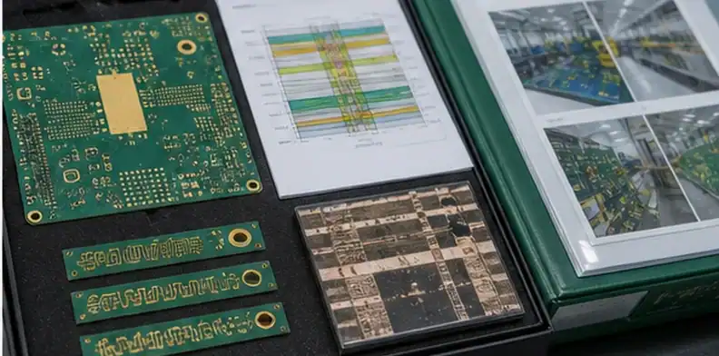
High-frequency performance is affected by more than laminate name. Surface finish, solder mask clearance, copper roughness, and launch geometry can all change loss, impedance, and repeatability. A buyer who only specifies Rogers or PTFE may still receive a board that is hard to tune because the surrounding fabrication details were left open.
The RFQ should state whether RF traces need solder mask clearance, whether ENIG or another finish is acceptable for the launch area, and whether copper foil roughness matters for the frequency range. For digital control layers these details may be less sensitive, but for RF launch and antenna paths they can decide whether a first article behaves like the simulation.
A useful supplier answer will not simply promise capability. It will say which surface finish is included, whether mask dams or openings are needed around RF structures, and whether the proposed copper foil supports the loss target. If the supplier asks to modify a mask opening or finish choice, that question belongs in the engineering approval record before the PO is released.
Surface rule: A high frequency hybrid PCB stackup is not quote-ready until the RF surface condition is defined together with the material stack.
Set the first-lot review before repeat orders
The first lot should create the record that later orders will follow. For a hybrid RF board, that record should include the final stackup, material lot or approved material family, impedance evidence, CAM exceptions, and any RF-sensitive fabrication notes returned by the supplier.
A buyer may accept a small first lot with extra review time, but repeat orders need a stable baseline. If the first lot was built with a substituted prepreg, adjusted dielectric thickness, different copper foil, or changed solder mask opening, those changes should not live only inside an email thread.
Ask the supplier to return a short manufacturing assumption summary with the first accepted lot. That does not need to expose proprietary process details. It should preserve the decisions the buyer must repeat: material, layer assignment, critical impedance layers, surface finish, evidence level, and any approved alternates.
For claim prevention, this connects to PCB lot traceability and PCB quality documents before shipment. A hybrid board is easier to defend when the first-lot record says what was actually accepted.
Repeat-order call: Treat the first hybrid RF lot as the master evidence package for the next build, not as a one-time prototype memory.
Use RFQ wording that forces a comparable supplier answer
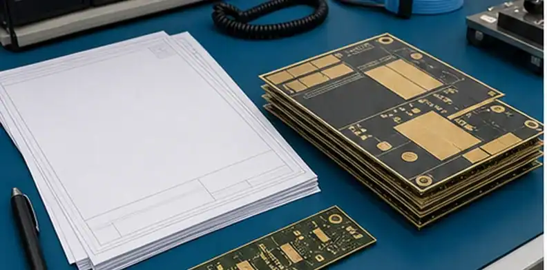
The RFQ should force the supplier to answer in a way purchasing can compare. A short message such as ‘quote Rogers plus FR4 hybrid’ leaves too many assumptions open. A better request names the RF function, material preference, layer role, impedance target, evidence package, and approval rule in one place.
Practical wording can be simple: quote the attached high frequency hybrid PCB stackup with low-loss material on the RF routing layers and FR4 or approved compatible material on non-critical layers. Confirm the proposed laminate and prepreg set, finished dielectric thickness, copper foil, surface finish, controlled-impedance evidence, and any CAM change needed before production release.
Add a decision line for alternates. The supplier may propose an equivalent material or thickness adjustment, but the buyer should require written approval if RF layer assignment, finished board thickness, impedance tolerance, or evidence level changes. This prevents a quote from becoming a different board during CAM.
For a founder or purchasing manager, this wording is useful because it turns a technical stackup into a commercial comparison. Two suppliers may both say they can build a hybrid RF board; only the one that returns clear assumptions, evidence, and exceptions is giving a quote the buyer can safely approve.
RFQ wording: Ask the supplier to confirm the exact mixed-material construction, not merely the ability to fabricate a high frequency hybrid PCB stackup.
FAQ
Can Rogers and FR4 be combined in one high frequency PCB?
Yes, but only when the selected materials, prepregs, lamination process, drill preparation, and RF layer placement are compatible. The RFQ should ask the fabricator to approve the exact construction rather than only approving the brand names.
Does a hybrid stackup always save money?
No. It can reduce premium material area, but added lamination control, impedance testing, cross-section review, and yield risk can reduce the saving. Compare total quote assumptions, not only laminate area.
Should RF traces be on the outside layers?
Often yes for antenna feeds, launch tuning, and inspection, but inner stripline can be better for shielding. The decision should follow the RF path, reference planes, via transitions, and supplier’s build capability.
What evidence should I request before shipment?
Request stackup signoff, impedance coupon data for critical layers, and cross-section or microsection evidence when the build risk justifies it. The evidence should refer to the released stackup, not a generic capability statement.
Related QueenEMS articles
- RF PCB manufacturer
- Supplier stackup signoff
- PCB impedance test report requirements
Send QueenEMS the hybrid RFQ package
If you have a high frequency hybrid PCB stackup for an RF, antenna, radar, or mixed RF/digital project, send the stackup drawing, material callouts, Gerber or ODB++ data, impedance targets, quantity, and evidence requirements through the QueenEMS contact page.
QueenEMS can review whether the RF layers, FR4 support layers, lamination boundary, controlled-impedance evidence, and supplier questions are clear enough for quotation before manufacturing assumptions become expensive to reverse.
Sources
- Rogers RO4350B laminate data
- iNEMI Hybrid PCBs for Next Generation Applications
- Altium hybrid stackup reliability
Written by the QueenEMS Engineering Team
Upload your files today · Free DFM check before production · Ship worldwide
Get your PCB prototypes in as fast as 24 hours. We handle FR4, Rogers, and Flex up to 60 layers — free prototypes for 2–4 layer boards, no minimum order.
Just upload your Gerber + BOM — we source every part, assemble, and inspect (AOI + X‑Ray) so you don't have to chase suppliers. Boards ship in as fast as 24 hours.