
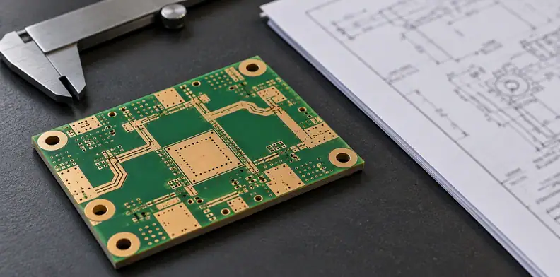
Quick Answer: Specify RF PCB phase matching as the phase difference between identified channels at the same frequency and temperature, after removing any intended offset and defining the measurement reference planes. Set separate limits for the remaining mismatch and its change from a reference temperature. Verify both from consistent phase data; equal routed lengths and a laminate TCDk value cannot establish the finished channels’ performance.
“Phase matched” can describe several different requirements. One buyer needs channels aligned at room temperature; another can calibrate their initial offset but needs that relationship to remain stable as temperature changes. Those orders need different acceptance statements even when their layouts look identical.
Why don’t equal trace lengths or a laminate TCDk value guarantee phase-matched channels?
Equal physical length controls only one contributor to electrical phase. Each channel also includes its dielectric environment, transitions and any launches or connectors inside the measurement boundary. Temperature can affect those elements differently. A laminate's thermal coefficient of dielectric constant describes material behavior; it does not qualify the relative phase of two finished channels.
Rogers describes temperature and frequency stability for its named RO3003 laminate. Such characterization is useful input for a circuit model. It is not a guarantee for every trace, transition and interface built with that material, and it does not replace the project's channel measurement.
Keep material choice in the specialty RT/duroid comparison. Here the decision comes after the construction is proposed: what exactly must the measured channel relationship satisfy? This article addresses separate, single-ended RF paths, such as two antenna-feed channels, rather than the two conductors of a differential digital pair.
What should “phase matching” mean in an RF PCB specification?
Name a reference channel, the transfer direction and the intended phase offset before defining an error limit. Compare channels at identical frequency and temperature points using stated reference planes. Then distinguish the residual mismatch at each condition from its change relative to a reference temperature; these quantities answer different acceptance questions.
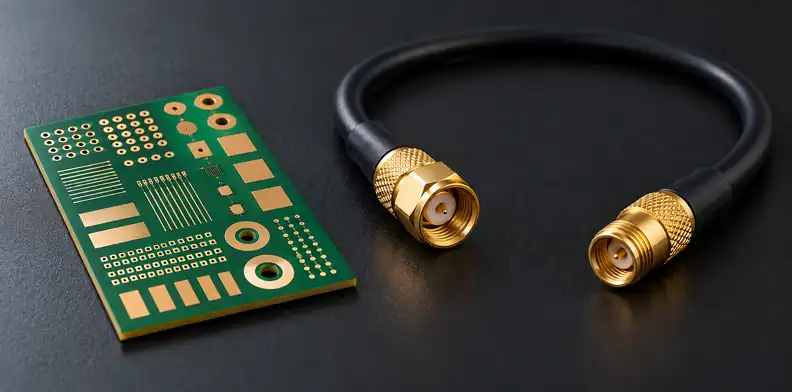
For channels A and B, define the residual as M(f,T) = φB(f,T) − φA(f,T) − θint(f,T). Here θint is the intended value of φB − φA, using the same sign convention, and it may depend on frequency. Allow it to vary with temperature only when the specification explicitly defines that dependence; otherwise it would absorb the thermal change being tested. A deliberately offset network should not be judged against zero before that design relationship is removed.
The thermal change is D(f,T) = M(f,T) − M(f,Tref). Preserve the chosen reference temperature Tref and calculate a separate result at each specified frequency. Averaging the whole band can conceal a local failure unless the specification explicitly uses that statistic.
Write whether the phase limit uses a consistent unwrapped branch or a circular phase error. Also state whether a calibration correction is permitted, where it is applied and whether it remains fixed throughout the thermal sweep. Quietly zeroing every temperature trace would remove the behavior the test was intended to evaluate.
How do you calculate phase mismatch and thermal phase tracking from VNA data?
Take each channel's transfer-phase data at matched frequency and temperature points, using consistent reference planes and phase branches. Subtract the reference channel and the intended offset to obtain mismatch. Subtract the reference-temperature mismatch again to obtain thermal change. Retain both results, because removing the initial offset can change the acceptance decision.
This worked example uses invented readings at one frequency, with an intended offset of zero. The reference is 25°C; the hot condition is called Thot because its actual temperature belongs in the project specification. None of the values represents a QueenEMS measurement.
| Condition | Unwrapped φA | Unwrapped φB | Mismatch M | Thermal change D |
|---|---|---|---|---|
| Reference, 25°C | −1050° | −1052° | −2° | 0°, by definition |
| Thot | −1090° | −1095° | −5° | −5° − (−2°) = −3° |
Suppose the example project permits ±6° residual mismatch but only ±2° thermal change. The hot result passes the first condition because its magnitude is 5°. It fails the second because the change has magnitude 3°. A report showing only “phase within 6°” would omit that failure.
Keysight's phase-format guidance explains that unwrapping compares adjacent data points. Excessive phase movement between points can make that process inaccurate. Preserve frequency resolution and branch handling rather than treating the analyzer's unwrapped display as proof that the acquisition was adequate.
Why can’t group delay or wrapped phase prove channels are phase matched?
Group delay describes the slope of phase with frequency, so equal group delay can coexist with a constant phase offset between channels. Wrapped phase is a display convention and needs an agreed comparison rule. Neither a delay trace nor a wrapped screenshot alone establishes the channel relationship across all required frequencies and temperatures.
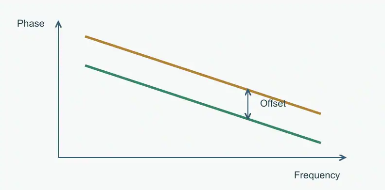
Consider two hypothetical responses with φB(f) = φA(f) + 10°. Their derivatives with respect to frequency are equal because the added 10° is constant. Their group delays therefore agree, while their phase difference remains 10°. A phase-offset requirement can fail even though a group-delay comparison passes.
A phase display confined to ±180° also jumps at its boundary. That jump is not necessarily a physical discontinuity. Conversely, choosing a convenient branch cannot repair missing frequency resolution or an inconsistent reference. Preserve complex data and the reduction convention so another engineer can reproduce the result.
Do not turn an arbitrary phase difference into a delay simply by dividing by 360 times frequency. That shortcut requires an appropriate delay model and phase reference; it is not a general replacement for evaluating a dispersive network's phase response.
How should an over-temperature phase test be set up so the data can be trusted?
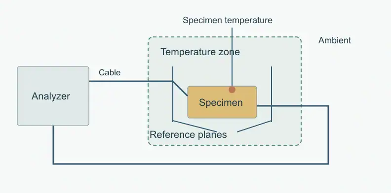
Define calibration reference planes and distinguish specimen temperature from chamber air and instrument temperature. Keep cable position and connector practice controlled, and agree how the specimen reaches a stable measurement condition. Otherwise a reported temperature-dependent channel difference may include changes in the measurement system rather than only changes in the printed circuit.
Keysight's measurement-stability guidance identifies temperature effects in the analyzer, calibration standards, device, cables and adapters. It also calls for calibration at the device connection and careful, repeatable connections. These controls belong in the test definition, especially when two channels are measured sequentially.
Ask which cables and adapters enter the heated region, which remain outside, and how their contribution is evaluated. Document any reconnection or calibration change. Compare a return-to-reference reading where the test plan uses one; a changed baseline needs investigation before assigning the shift to the laminate.
Stabilization time, temperature steps and uncertainty allowance must come from the test provider's validated method and product requirements. Copying a generic instrument warm-up or ambient-temperature recommendation does not define a finished-board chamber test.
What should your RFQ and test data package include?
Supply the channel and reference definitions with the fabrication files, proposed construction and separate mismatch and thermal-change requirements. Name the test owner and request data that preserves each channel, frequency and temperature condition. A pass/fail summary should be traceable to the underlying complex measurements and the stated calculation, rather than replacing them.
The following proposed record supports an independent recheck. It is not a universal test standard or an offer of a QueenEMS laboratory service.
| Record field | Information to preserve |
|---|---|
| Path identity | Channel, reference channel, ports, transfer direction and drawing revision |
| Measurement boundary | Reference planes, included launches, fixture treatment and calibration record |
| Conditions | Frequency grid; specimen temperature, reference temperature and stabilization rule |
| Original data | Complex S-parameters, such as applicable Touchstone files, for each condition |
| Reduction and decision | Intended offset, phase convention, M and D calculations, limits and disposition |
If the customer or its chosen laboratory owns the test, state that in the RFQ. If that laboratory is separate from your own team, obtain its method and scope in writing before relying on its results. Routine board inspection or a general functional-test option does not establish over-temperature RF phase capability. Confirm the fabrication route and any separate measurement arrangement before ordering.
Frequently Asked Questions
Does a low-TCDk laminate guarantee phase-matched RF channels?
No. Material behavior is one input. Geometry, transitions and the interfaces inside the measurement boundary also affect the finished paths. Use material data for modeling and check the specified channel relationship on representative hardware.
Should an intended phase offset be removed before comparing channels?
Yes, when the requirement concerns error relative to that offset. Specify its value or frequency-dependent function, the sign convention and reference channel. Preserve the uncorrected data as well as the residual calculation.
Can a phase-matching limit omit the temperature range?
No. Omitting it leaves thermal acceptance undefined. State the test temperatures, reference condition and stabilization rule, with separate requirements for residual mismatch and its temperature-dependent change.
Is RF channel matching the same as differential-pair skew?
No. This guide compares transfer phase between separate single-ended RF paths. A differential link has its own balance and timing requirements; its acceptance should not be inferred from this channel comparison.
Does a PCB quotation include phase testing over temperature?
Do not assume so. A fabrication quotation and DFM review cover the board, not over-temperature phase measurement. Do not infer this test from routine board inspection or from a general functional-test listing. Agree the customer-appointed test owner before placing the order.
Send your released files for a quote and free DFM review.
Send Gerber, stackup and phase-matching requirements for review. Include temperature conditions and the evidence required to accept the board.
For assembly, add the BOM and phase-sensitive component requirements. Identify who will verify the populated circuit across the stated temperature conditions.