
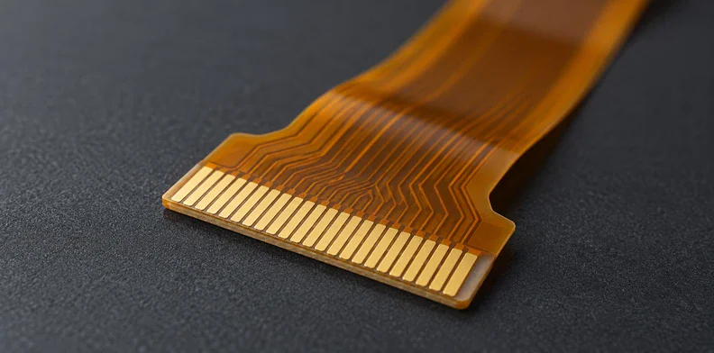
Quick Answer: For flex PCB ACF bonding, specify both mating pad arrays, their permitted displacement, the contact finish and the support beneath the joint. Check the remaining overlap against the selected film’s requirements, then qualify electrical contact, adjacent-contact insulation and adhesion separately under the product’s required exposures. The flex drawing controls the supplied termination; the bonding partner must establish its film and process combination.
A bare-flex continuity report ends at the flex terminals. It cannot tell you whether conductive particles will make durable contact with a second part after heat and pressure are applied. Before ordering the flex, join the two interface drawings and decide how the completed connection can be tested.
What does ACF bonding require from a flex termination?
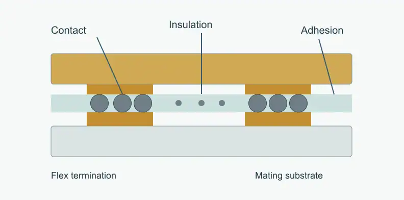
The termination must present pads that, together with the opposing mating pads, give enough contact area, separation and suitable surface height for the selected film. Heat and pressure capture conductive particles between those pads, while the adhesive holds the assembly together. Film selection therefore depends on the mating materials and geometry as well as the flex itself.
Dexerials describes these three functions in its ACF material explanation: adhesion, conduction through the connection, and insulation between neighboring contacts. Particle constructions and resin systems vary. A film described as suitable for one display interface does not automatically suit a different board finish or contact area.
Name the connection first: flex-to-board, flex-to-glass or another pairing. The mating electrode can change both the material choice and the available inspection access. Keep this electrical joint separate from the core, coverlay and stiffener bonds discussed in the flex adhesive selection guide.
Which pad geometry belongs on the flex and mating drawings?
Define both pad arrays, including width, length, pitch, gap, position and the reference features used for alignment. Then assess their overlap at permitted manufacturing and assembly offsets. Compare the resulting contact area and separation with the chosen film's requirements; nominal pitch alone cannot establish that the complete array is suitable.
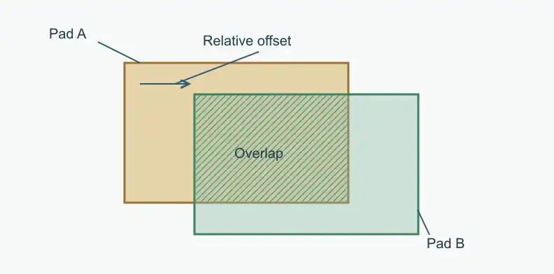
The following proposed worksheet uses equal rectangular pads and a translation in two directions. It deliberately omits rotation, etch variation and thermal growth. Dimensions are hypothetical, not QueenEMS capabilities or recommended design limits.
| Example input or result | Value | Calculation |
|---|---|---|
| Pad width × length | 0.30 × 1.00 mm | Nominal area = 0.300 mm² |
| Relative displacement | 0.04 mm across; 0.15 mm along | Remaining overlap dimensions = 0.26 × 0.85 mm |
| Overlap area | 0.221 mm² | 0.26 × 0.85 |
| Fraction of nominal area | 73.7% | 0.221 ÷ 0.300 × 100% |
For this simplified case, overlap is max(0, width − absolute sideways displacement) multiplied by max(0, length − absolute lengthwise displacement). If either term reaches zero, those two rectangles no longer overlap. Different pad sizes require their actual intersecting boundaries instead.
A real review also includes pad-width tolerances, rotation and array pitch error. Inspect the outermost contacts: a pitch mismatch can accumulate across the array even when the center aligns. Add measured process-temperature displacement where relevant. The film supplier and bonding partner must decide whether the resulting geometry supports their qualified contact and insulation requirements.
Which finish, support and alignment details affect the bond?
Show the specified contact finish, exposed-pad region, local thickness steps and supporting surface on the drawings. The bonding tool needs access to a supported area, and its alignment system needs visible reference features. Film-specific pad-height and surface requirements must be checked with the bonding partner before the termination is released for manufacture.
Do not select a finish from its color or its solderability reputation. Confirm the actual metal stack, surface condition and relevant thickness requirements against the selected film and mating electrode. The NPL study discussed below used ENIG on its particular test vehicle; that choice does not qualify every ENIG-and-ACF combination.
Review the coverlay boundary and any adhesive encroachment beside the contacts. A permanent stiffener and a temporary backing fixture are different ways of supporting a tail; neither should be added automatically. Their edges, thickness and position must suit the bonding tool and the final flex exit. Keep fiducials accessible after the film and both parts are positioned.
Who owns the ACF process and what should be agreed before release?
Agree which party controls each drawing and process requirement before ordering the flex. The fabricator supplies the specified termination; the bonding partner establishes and controls the film, tooling and bonding cycle. The product owner approves the interface and its qualification. Changes affecting either side must return to the responsible parties for review.
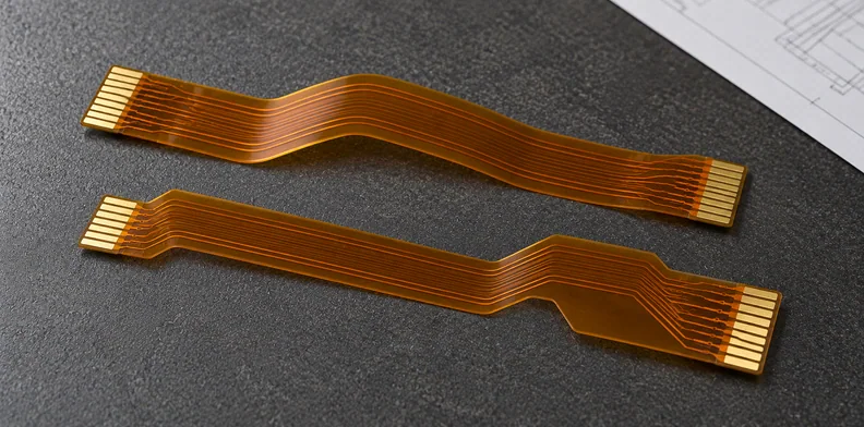
An agreed division might look like this. It is a suggested allocation, not a universal contract or evidence that QueenEMS performs the bonding operation.
| Item | Confirmation needed |
|---|---|
| Flex pads, finish and support | Fabricator confirms the released drawing and feasible tolerances |
| Film, mating electrode and bonding cycle | Film supplier and bonding partner confirm the qualified combination |
| Finished-joint limits and exposure plan | Product owner approves requirements with the test provider |
| Film, finish, tooling or drawing change | Affected owners review its dimensional and qualification impact |
Use the flexible PCB manufacturing service for the fabrication review. Film selection, bonding and finished-joint qualification require an identified provider and an agreed scope. No single temperature, pressure or pitch applies across all ACF products. Record how the bonding partner verifies the temperature actually reached at the bond line, because the tool setting and the joint condition are separate observations.
How should contact and insulation be measured on an ACF bond?
Plan electrical access before fabricating the test vehicle or product. A daisy-chain reading includes several contacts and the intervening tracks, so its result must retain that measurement topology. Test adjacent-contact insulation separately. Before adopting a production screen, establish whether the method can distinguish the defective joint conditions the project needs to detect.
An original NPL investigation of ACF assessment methods provides a useful lesson. Its flex-to-board meander included access pads for measuring separate segments. A nonlinearity measurement distinguished some poorly bonded samples that were less apparent from DC resistance. The VNA-based TDR method tested in that study did not distinguish the imposed bonding-pressure variation.
That finding concerns one specimen and test setup. It does not make nonlinearity testing compulsory or establish that every TDR method is unsuitable. It shows why a familiar electrical test needs a demonstrated connection to the defect being screened.
If the drawing permits only a full-chain reading, label it accordingly. Do not divide the chain resistance by the number of joints and report an individual contact value without accounting for tracks, leads and the measurement's limitations.
What evidence qualifies contact and adhesion after aging?
Record electrical contact, neighboring-contact insulation and mechanical adhesion as separate results before and after the product's defined exposures. Specify the specimens, methods and acceptance limits with the bonding and test providers. Initial continuity and initial peel strength answer different questions, and neither alone demonstrates the completed connection's lifetime under the intended operating conditions.
Use a coverage matrix to expose missing observations rather than turn an unperformed test into a pass. This proposed template leaves the exposure program and limits to the project.
| Characteristic | Initial record | After defined exposure | Specimen identity and method |
|---|---|---|---|
| Electrical contact | Chain or accessible segment readings | Same topology; change and interruptions if monitored | Contact/segment map, instrument and conditions |
| Adjacent insulation | Named neighboring conductors | Result under specified measurement conditions | Pairs, bias and measurement method |
| Mechanical adhesion | Agreed peel or other strength result | Retained strength on assigned specimens | Loading geometry, rate and failure location |
| Relevant flex loading | Termination and support arrangement | Electrical and joint condition after the defined motion | Fixture, motion and specimen history |
For example, a qualification package containing post-exposure chain resistance but only initial peel data leaves retained adhesion unresolved. Request the missing result or a documented product-owner disposition. The NPL paper identifies aging as future work, so its reported electrical findings cannot supply that missing aging evidence.
Frequently Asked Questions
Can an ACF-bonded flex be reworked?
It depends on the film chemistry and the approved removal process. Dexerials notes that rework suitability differs between ACF products, so a removed and rebonded joint should not be assumed equivalent to the original. Agree the allowance and verification with the bonding partner before release.
Is DC resistance alone enough to accept an ACF bond?
It may detect an open or high-resistance connection, but its screening sensitivity needs validation. The cited NPL study found some poorly bonded samples that were less apparent from DC resistance than from its nonlinearity measurement.
What should accompany a flex PCB RFQ for an ACF termination?
Provide flex fabrication files, the mating-pad drawing, film identification or requirements, support details and the bonding partner’s interface requirements. State which tolerances remain open. Include a BOM only when requesting assembly.
Does a flex PCB fabrication quote include ACF bonding?
Do not assume it does. Identify who supplies the film, performs the bonding and qualifies the completed joint. Treat a fabrication quotation and DFM review as covering the bare flex termination; arrange film supply, bonding and joint qualification with the parties you identify.
Send your released files for a quote and free DFM review.
Send Gerber, flex stackup and the ACF interface drawing for review. Mark contact geometry, exposed areas and the applicable interface requirements.
If ACF bonding or component assembly is requested, provide the mating-part and placement details. Ask us to confirm the specific joining and assembly scope.