
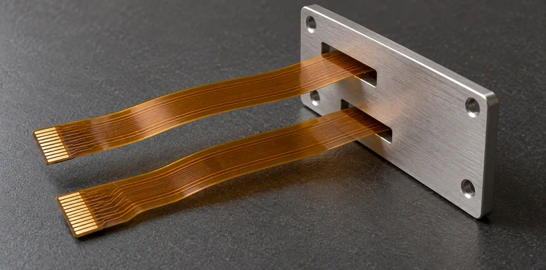
Quick Answer: Use a flex circuit feedthrough drawing to identify the sealed assembly and its separately called-out flex parts. Quote each flex item from its own controlled fabrication package, and apply a “not controlled this side” note only where its leader points. Return missing spacing, flat-outline and pin-map definitions to the design owner instead of deriving them from assembly views.
A dual-flex assembly drawing can identify the parts to order while leaving their fabrication definitions elsewhere. Here, the assembly drawing is the feedthrough supplier's mechanical drawing of the sealed part, not a PCBA placement drawing used to populate a board. Before requesting bare FPCs, find its child documents. The following example uses a public vendor drawing to separate an assembly's stated features from the information a flex fabricator still needs.
What does a flex circuit feedthrough drawing define for each flex?
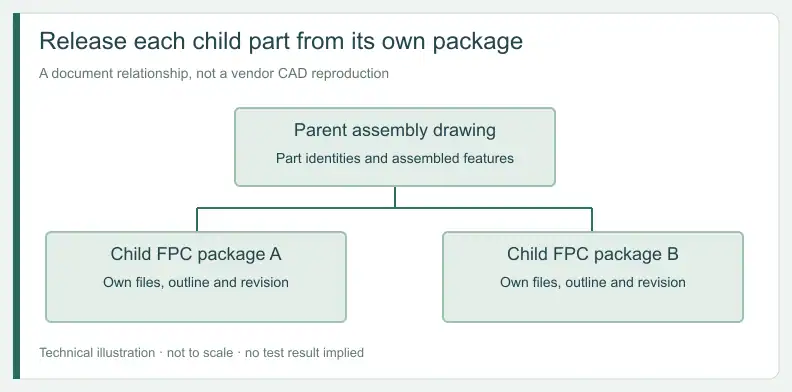
A flex circuit feedthrough drawing can define the parent assembly without supplying the flat artwork for its child circuits. Read each callout at its stated level. Assembly dimensions, connector notes and test requirements help identify the assembly; the flex order still needs the controlled fabrication files for each named circuit.
The public PAVE dual-flex assembly drawing is an undated vendor example. It calls out separate flex cable assemblies, shows housing and installation-port views, and carries notes whose leaders identify particular regions. Confirm these readings on the native drawing with its owner. Do not edit or re-dimension the vendor's CAD.
Note interpretation key for this example
| Drawing element | Location or level | Reading category | Consequence for the flex order |
|---|---|---|---|
| Flex-spacing note | Atmosphere free span, at its leader | Explicitly uncontrolled | Refer installation constraints to the integration owner |
| Vacuum-side flex spacing | Opposite free span | Not given | Request definition if fit needs it |
| Seal-plane section dimension | Section through the assembly | Referent needs confirmation | Do not use as a free-span pitch |
| In-line plug note | One assembled end | Stated form only | Request the separate pin map |
| Right-angle plug note | Opposite end; same facing direction | Stated form only | Do not infer contact side or net order |
| BOM flex OAL | Each flex assembly’s description | Part description | Find that part’s controlled flat outline |
| Overall and flange-to-connector dimensions | Assembly elevation | Assembly-level dimensions | Keep separate from flex cut length |
| General tolerances | Finished assembly | Assembly-level only | Use the flex drawing for fabrication tolerances |
| Leak, temperature and void notes | Sealed assembly | Outside bare-FPC acceptance | Keep with the seal owner |
| Revision level | Parent title block | Assembly identity only | Request each child package’s revision |
How do you match each BOM flex item to its fabrication package?
Map every flex item by its BOM identity to a fabrication package and revision before combining quantities for a quote. Different part numbers remain separate order items until the design owner confirms their relationship. Shared connector styles do not establish identical or mirrored copper artwork, and the assembly drawing does not supply that confirmation.
The example lists different flex part numbers and different overall-length descriptions. It shows no revision beside either flex item. Those entries identify child parts; they do not replace the child drawings.
Per-flex release map
| Record for each flex item | Where it should come from | If missing or unconfirmed |
|---|---|---|
| BOM item and part number | Parent assembly BOM | Hold: confirm which flex is being ordered |
| Fabrication package and revision | Child Gerber or ODB++, stackup and fabrication drawing | Hold: request from the design owner |
| Flat outline and its tolerances | Child fabrication drawing | Hold: do not derive from assembly views |
| End identity | Parent atmosphere and vacuum labels, cross-referenced to the child drawing | Quote with a listed open item |
| Connector form and assembled facing | Parent connector notes | Quote with a listed open item |
| Pin one, contact side and net map | Pin map, netlist or child assembly documents | Hold if connectors are to be assembled; otherwise a listed open item |
| Free-span spacing and restraint | Integration owner | Quote with a listed open item; installation only |
Use the parent drawing's atmosphere and vacuum labels to name the ends in this record. Keep a missing document as an open item rather than recreating it from the pictured assembly.
What does “spacing not controlled this side” actually limit?
Apply the spacing note to the free span identified by its leader. In this example, that leader points just left of the flange in the elevation view, on the in-line plug side labelled atmosphere in the lower view. It does not turn the spacing into a fabrication tolerance, and it does not govern other notes that also say “this side.”
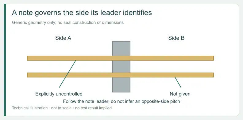
The drawing uses “this side” in several notes. Follow each leader independently: connector form, flex spacing and a seal-surface note do not share one global instruction simply because they use the same words.
If the installation requires a fixed separation in the explicitly uncontrolled span, return that requirement to the integration and drawing owners. The fabricator should not silently add a dimension or decide how the free tails must be restrained.
Is the other side controlled when the drawing gives no spacing?
An omitted spacing dimension leaves the opposite free span undefined by that view. It does not establish a controlled pitch merely because another side is explicitly uncontrolled. Look for a dimension whose endpoints and datum actually govern the intended location, and ask the drawing owner to resolve any missing definition needed for fit.
The vacuum-side view supplies no direct flex-to-flex spacing dimension. A centerline-referenced dimension appears in the seal-plane section, but its referent requires confirmation with the drawing owner. Do not carry it into either free span or the flex fabrication drawing as a pitch.
Keep “not given” and “explicitly uncontrolled” as separate entries. The first identifies missing information for a decision; the second reports an explicit boundary in the supplied drawing.
Can assembly-view lengths set the flex circuit cut length?
Use the flex fabrication drawing for the flat outline. A BOM overall-length description, an assembly elevation dimension and a flange-to-connector dimension identify different quantities. A numeric string in the parent description code adds no authority to convert between them. Their endpoints and document purpose must be resolved before they enter a fabrication order.
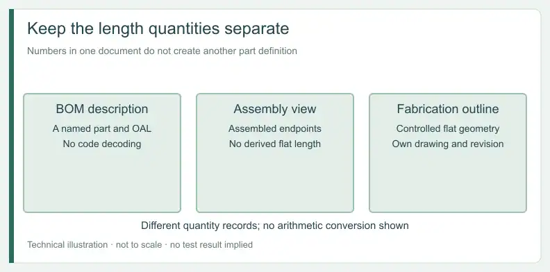
The example contains these different length descriptions. Do not add or subtract them to construct a flat circuit or announce a dimensional mismatch. Connectors, assembly geometry and the separately identified child part all need their own definition.
The title block's general tolerances apply to the finished assembly. They are not a source for the bare flex outline tolerance. Keep the fabrication revision and its controlled dimensions with the corresponding BOM item.
What do the connector notes define, and what do they leave open?
The connector notes define assembled form and facing: in-line plugs at one end, right-angle plugs at the other, with the latter facing the same direction. They do not identify pin one, contact face relative to a copper side, or net order. Request those definitions from the electrical and assembly documents for each flex item.
A matching mechanical silhouette cannot settle whether conductors must be shared, mirrored or rearranged. Cross-reference the connector identity, pin map and circuit artwork before requesting assembly.
A quote for bare flexible circuit fabrication covers the circuit itself. Keep any connector assembly request explicit in the BOM and order scope; the feedthrough supplier retains the sealed assembly's definition.
Which acceptance belongs to the bare flex and which to the seal?
Set bare-flex acceptance in its own order documents, with the fabrication dimensions and electrical test scope that apply to that item. The example's leak-test conditions, seal-related notes and operating information concern the assembled feedthrough. They do not define acceptance of an unsealed circuit or establish every condition of the installed equipment.
The drawing's leak-test note names an O-ring condition, and a separate note states that tests are performed at room temperature. The operating temperature range appears as a reference note. Preserve that distinction with the seal supplier; no leak rate or operating limit is transferred here.
For the separate contamination question, use the guide to evidence for low-outgassing constructions. A sealed-assembly leak result and a material or construction outgassing record answer different questions.
Frequently Asked Questions
Can a flex fabricator quote from the assembly drawing alone?
No. Each flex item needs its own fabrication package and revision. QueenEMS does not reverse engineer circuit artwork from assembly views.
Should a buyer add a tolerance where spacing is not controlled?
Return that decision to the drawing or integration owner. The fabricator should not silently add a spacing requirement.
Are two flex circuits identical if their connectors look alike?
No. Connector appearance does not establish identical or mirrored artwork. Match each BOM item to its own controlled package.
Does an assembly leak-test pass qualify the bare flex?
No. Sealed-assembly acceptance and bare-FPC acceptance cover different items and are set in different documents.
Send your released files for a quote and free DFM review.
Send the flex stackup and feedthrough drawing for review. Mark the sealing boundary, finished dimensions and proposed construction for confirmation.
If assembly accompanies the flex order, identify fitted parts and the sealing-interface owner. Confirm the quoted scope; sealing qualification needs separate agreement.