
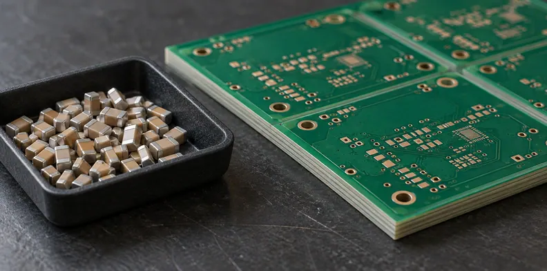
Quick Answer: Before a discrete passive chip is embedded, identify where it enters the actual fabrication route and which later operations act on it. Match the condition record and evidence to each operation, including any further build-up or outer-board assembly in that route. Leave an unmatched step open for the embedding qualification owner rather than treating evidence for another operation as a pass.
A request for “thermal history” can hide several different manufacturing questions. The record for a loose component, the first embedding press and later assembly may all describe different events. Embedded component lamination exposure is easier to review when the buyer follows one named part through the released route.
This guide concerns physically embedded discrete passive chips before order release. It uses historical development examples to identify separate operations, without supplying manufacturing parameters or a qualification procedure.
Why reconstruct the route for one named part before ordering?
An embedded component lamination exposure record identifies which operations act on the selected device and what evidence addresses each one. A board's layer count does not establish that history. Start with the exact passive part and its entry point, then follow it through the fabrication and assembly operations that the released route actually includes.
Operating bias and temperature belong in a separate electrical-selection record. Here the question is which manufacturing event a document describes. Bare-die preparation and known-good-die supply are outside this scope.
Keep the component identity beside the route revision. A revised route can change the operations acting on the same component, while a component substitution can change which evidence applies to an unchanged route. Review the affected rows when either changes.
At which step does the component enter the embedding route?
Identify the placement or chip-attach operation at which the device becomes part of the construction. The historical sources show a part placed onto foil or a carrier before embedding lamination. Record the fabricator's actual step name and the part state there, rather than assuming that every earlier operation on the board also acted on it.
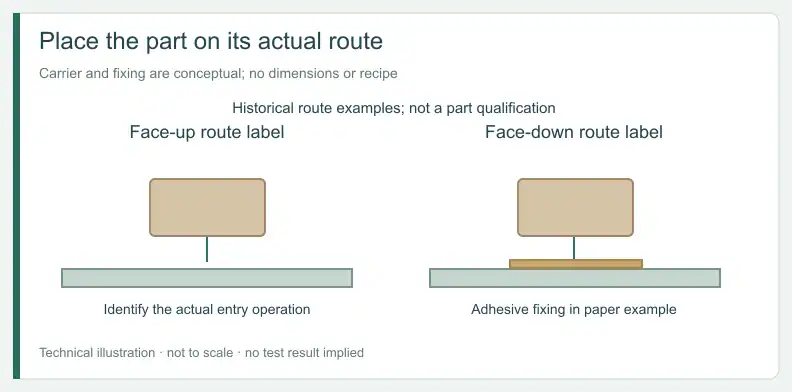
The IPC-hosted HERMES development paper and accompanying slides distinguish face-up and face-down flows. The face-down description uses adhesive fixing on a carrier; both flows then show embedding by lamination followed by drilling, plating and structuring. These are historical examples, not an IPC process standard or a preferred route.
Use the released process description to locate your part's entry. Evidence generated before that entry, such as data on the loose component, describes a different part state, so its relevance to later rows needs explanation. Do not add an assumed fixing material or cure operation when the route does not name one.
Is the first embedding lamination the only one the part sees?
Not necessarily. The sources describe an embedded core that can become an inner-layer core within a further multilayer construction. Any later build-up lamination acting on that core belongs in the part's route record. Whether those operations exist, and how they are named, comes from the actual construction rather than from the example flow.
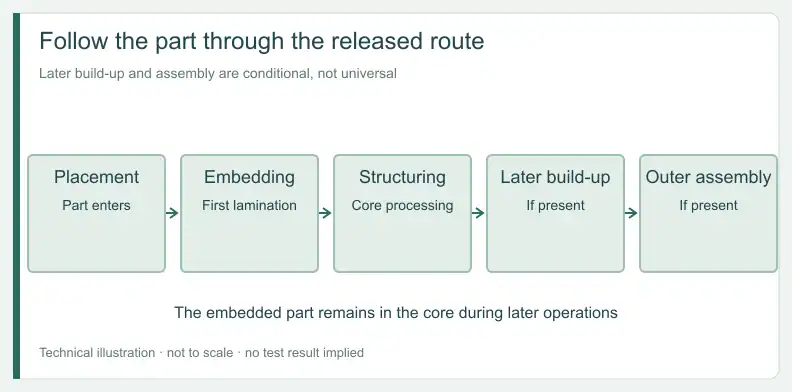
HERMES shows the embedded core inside a subsequent multilayer board. The maker example also notes that later HDI or multilayer build-up is possible. Neither source gives every customer board the same sequence.
Route-exposure map for one passive part
This is a suggested buyer map. Replace the example step labels with the fabricator's labels, add the relevant released-route operations and identify the named record holder.
| Example step | Acts on this part? | Part state | Condition record and holder | Evidence and origin | Decision owner | Disposition |
|---|---|---|---|---|---|---|
| Placement or fixing | Confirm | On foil or carrier | Enter record ID and holder | Enter item and origin | Enter owner | Select from caption list |
| First embedding lamination | Confirm | Becoming encapsulated | Enter record ID and holder | Enter item and origin | Enter owner | Select from caption list |
| Structuring and interconnect steps | Confirm | Inside embedded core | Enter scoped step and holder | Enter item and origin | Enter owner | Select from caption list |
| Later build-up, if present | Yes / no / unknown | Inside embedded core | Enter each relevant step | Enter item and origin | Enter owner | Unmatched stays open |
| Outer assembly, if present | Yes / no / unknown | Inside multilayer board | Enter scoped operation | Enter item and origin | Enter owner | Unmatched stays open |
Which later assembly operations still act on a buried part?
Outer-board component assembly happens with the embedded part already inside the board. Include the relevant operations if they belong to the agreed route, even though the buried part itself is not being surface-soldered. The record should identify those operations separately from the earlier placement and embedding steps, with their own evidence and owner.
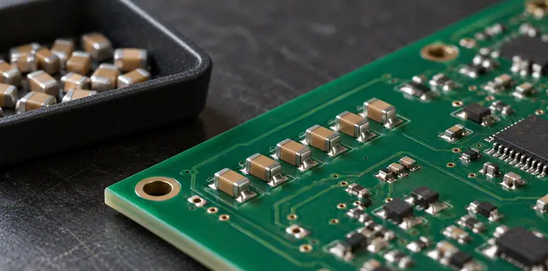
HERMES describes external SMD components assembled on both sides after the embedded cores are incorporated into the board. That establishes a sequence in the example. It does not provide an assembly profile for your component or prove its tolerance to one.
If the proposed route includes repair or another later operation, identify it explicitly. The development project's repair objective is not evidence that a particular embedded part survives a repair process.
What does a pick-and-place stress test actually show?
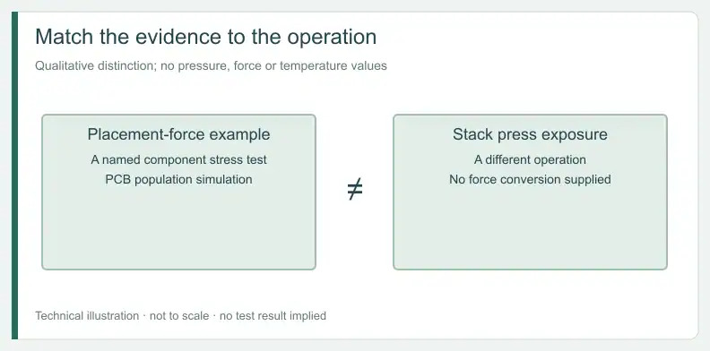
The AVX paper describes a mechanical force test intended to simulate pick-and-place during PCB population. That is the operation the source names. It reports no lamination temperature, pressure or duration, so the result cannot close an embedding-lamination row merely because both events involve mechanical loading of a component.
The historical Kyocera AVX embedded-capacitor paper illustrates the stress arrangement with a test head acting on a supported part. Its wording does not settle which placement event it models. Keep that ambiguity in the evidence record rather than assigning the test to the first embedding placement by assumption.
The same list of mechanical properties also names flexure and thermal cycling. A named property category is different from the condition record for a particular manufacturing operation. Its relevance needs a scope match, not a shared word such as “stress.”
How do you match each piece of evidence to its operation?
Label the document by the operation it names, its origin and the construction it covers, then compare it with the relevant route row. Evidence about a different operation leaves that row open. A maker result, a fabricator condition record and a buyer measurement answer different questions, even when they refer to the same component.
Evidence-to-operation reading key
The first four rows describe evidence types from the historical maker example. The soldering-profile and project-record rows, and every disposition, are buyer suggestions.
| Evidence held | Addresses | Does not establish | Origin | Suggested disposition |
|---|---|---|---|---|
| Pick-and-place stress test | Named placement force event | Lamination exposure | Historical maker test | Lamination row stays open |
| Thermal-cycling or flexure result | Its stated mechanical check | A particular route operation | Maker test | Check scope |
| Maker reliability summary | The reported example | Another part or process | Maker statement | No automatic transfer |
| Published embedded-capacitor section | The illustrated construction | Your part’s route tolerance | Historical maker image | Keep as context |
| Soldering or reflow profile | The operation it specifies | Embedding approval | Maker data | Refer to qualification owner |
| Lamination condition record | That step and route | Part tolerance to it | Fabricator project record | Owner evaluates applicability |
| Buyer measurement | What was measured and labelled | Anything outside that test | Buyer evidence | Owner evaluates applicability |
When should an unmatched route step hold order release?
Hold or refer the order when an operation acting on the part has no condition record, only evidence for another operation, or an unresolved applicability question. The embedding qualification owner must document how each open row is resolved. A blank cell is not a pass, and a route description alone does not establish component tolerance.
The fabricator identifies the route and available condition records. The component maker supplies the applicable part data. The embedding qualification owner decides whether the combination supports release or needs more evidence.
After that pre-release decision, the separate guide on what buyers can verify after a part is buried covers the later evidence boundary. This route record does not replace that inspection decision.
Frequently Asked Questions
Does a maker’s preconditioning document cover lamination?
Read the operation and specimen the document names. If it does not address the proposed lamination, that route row remains open. Its relevance requires an owner decision rather than a new meaning assigned to the document.
Does the first embedding lamination cover later build-up?
No. Identify any later operation acting on the embedded core and match evidence to it separately. A result associated with the first step does not identify the conditions or applicability of a later one.
Does a pick-and-place force test cover lamination pressure?
No. The cited maker paper describes placement loading. It does not make that test a lamination condition record or establish tolerance to the temperature, pressure and duration of the proposed embedding operation.
Does an embedded-capacitor image prove my part will survive?
No. The historical section illustrates a construction. It does not identify your component, your released route or the evidence needed for that combination. Retain it as context and resolve the actual part's route rows separately.
Send your released files for a quote and free DFM review.
Send stackup, component locations and the lamination exposure record for review. Ask us to confirm feasibility against the released construction.
Identify embedded parts and their supplier in the BOM. Agree who places them during fabrication and which later assembly operations are requested.