
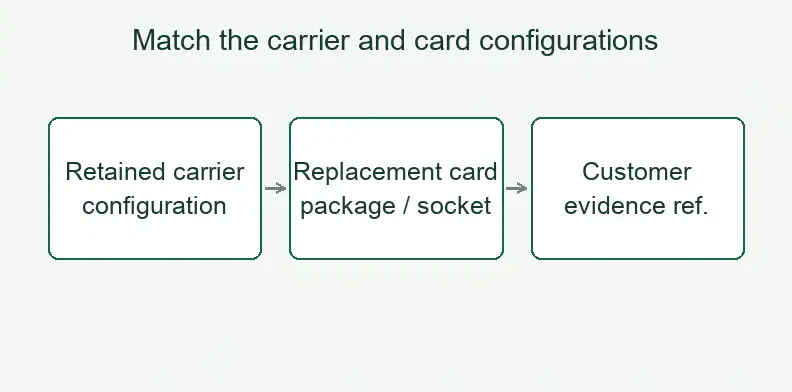
Quick Answer: For a replacement DUT daughtercard, approve the carrier’s actual power/jumper configuration with the card’s exact package/socket variant. Identify that pair separately from the two board revisions, using customer-approved interface references and pair-specific evidence. If the current configuration or approval is unknown, keep the pairing on hold for the customer’s design or test owner.
The retained carrier is part of the reorder decision even when it is not being purchased again. Its current configuration needs to appear in the approval for the replacement card, alongside the intended package and socket.
Why isn’t a matching outline enough to approve this replacement?
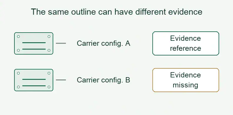
Approve the replacement for a specific carrier state and card variant, even when the outline and both board revisions are unchanged. The carrier may have been rewired since card approval, or the old order may lack its configuration. Record the actual power/jumper state before treating the replacement as approved.
Golden Gate Graphics documents a Trillium load-board arrangement with a ring-shaped halo and smaller daughtercards for different device packages. The halo remains broadly common across packages, but its jumper-wire configuration varies with the power supplies used. The card and the retained halo therefore need more description than their outlines.
The purchasing recommendation here is to identify the permitted configuration pair. Approval of one card variant with one carrier state should not silently become approval of every other state. Geometry and board revisions remain necessary references, while the current power/jumper state adds a separate input to the decision.
Which interface references belong to the specific pairing?
The documented Trillium example uses tester probes directly on daughtercard signal lands, while power arrives through the halo, bracket and edge fingers. Reference the approved signal contact, power entry and retained hardware for the pairing being ordered. Those references describe its interfaces; the combination record still needs the applicable carrier configuration and card variant.
In the halo/daughtercard system documented by Golden Gate Graphics, the bracket provides mechanical and electrical connection, and the author explicitly says it is not shown. The photos and description establish one real arrangement. They do not supply a controlled bracket drawing, power map or replacement-card approval record. The project year is also unstated.
For your order, use the customer’s released interface and hardware references. Keep their approval attached to the relevant configuration pair. Datum selection, tolerance allocation and mating qualification belong in the separate connector alignment review; this record consumes those decisions without choosing new fit limits.
How does the carrier’s current power configuration change the pairing?
The carrier configuration identifies the power arrangement that will actually be used with the replacement. In the Golden Gate example, jumper wiring depends on the supplies. A carrier part number and revision therefore may leave that arrangement unspecified. Ask the customer’s owner to identify the current configuration and the approval that applies to it.
Use a configuration ID that points to the released power/jumper definition. If the retained carrier has been modified, reconcile its observed state with that definition. A photograph can document what is present, but the customer’s electrical owner must determine what those connections mean and whether an existing approval covers them.
If the state is unknown, record “evidence missing” for the proposed pairing. That is different from a documented “not approved” decision. The responsible engineer can accept earlier evidence, request further support or restrict use. Preserve that decision and its reference.
Which package or socket variant is being approved with it?
Identify the intended device package and socket variant alongside the replacement card’s part number and revision. Those fields describe the card-side configuration being paired with the carrier state. A board identifier can leave the fitted socket ambiguous, particularly where a footprint supports more than one socket or the assembly population can vary.
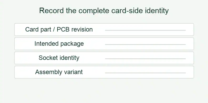
The Golden Gate example includes a daughtercard footprint that accepts three PLCC socket variants. This is a case-specific reason to identify the intended socket separately from the bare PCB. It does not establish interchangeability of those sockets in another design, or permission to use every variant with every halo power configuration.
Use the exact socket identification and assembly variant approved by the customer’s owner. If the purchase covers a bare card, the record can still name its intended application while the quotation stays limited to PCB fabrication. If another party fits the socket, make the approved variant available to that party. Keep socket footprint, hole and contact design decisions in the released engineering data.
What should the configuration-by-variant approval record contain?
The record should identify one actual carrier configuration and one specific replacement-card variant, then state whether that pair is approved, not approved or awaiting evidence. Include the pair-specific evidence, approving owner and restrictions. Keep unassessed combinations visible so a successful build or an approval for another pair cannot be mistaken for permission.
The following compatibility record is an editorial procurement suggestion. Golden Gate provides the implementation facts behind the question, not this form or a compatibility standard. The customer’s owners supply the limits, evidence and approval.
| Pair record field | Customer-controlled entry |
|---|---|
| Retained carrier state | Carrier PN/revision and actual power/jumper configuration ID |
| Replacement-card variant | Card PN/revision, intended package, socket ID and assembly variant |
| Applicable interfaces | Released signal-contact, power-entry and retained-hardware references |
| Pair-specific disposition | Approved / not approved / evidence missing |
| Basis and authority | Evidence reference/date, signal and power approvers, combination decision owner |
| Restrictions or open items | Customer-defined permitted configuration, conditions and unresolved questions |
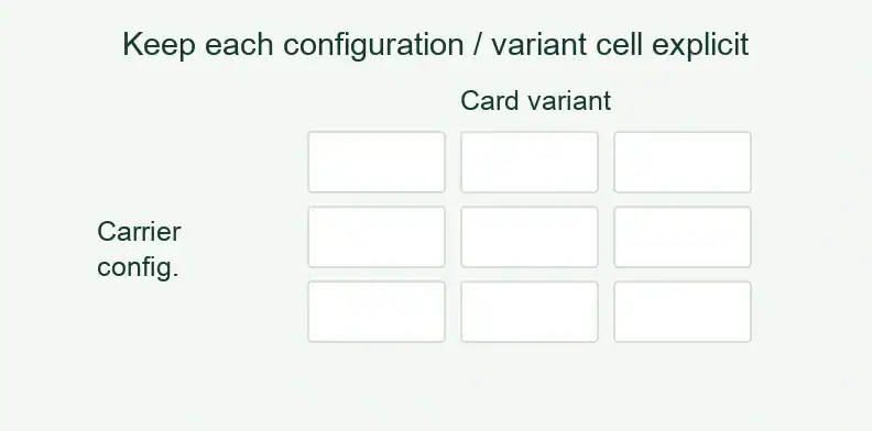
A configuration-by-variant grid is another view of the same record. Use actual configuration IDs for rows and exact card variants for columns. Each cell points to its own disposition and evidence. The blank template below contains no real approvals or test results.
| Actual carrier configuration | Card variant [A ID] | Card variant [B ID] |
|---|---|---|
| [Carrier PN/rev + power/jumper ID] | [Status + pair evidence reference] | [Status + pair evidence reference] |
| [Carrier PN/rev + other power/jumper ID] | [Status + pair evidence reference] | [Status + pair evidence reference] |
Do not copy approval across a row because the carrier is unchanged, or down a column because the card is unchanged.
What should you send a fabricator when ordering the replacement card?
Send the released replacement-card manufacturing data with references identifying the retained carrier configuration and approved card variant. Make the fabrication and assembly scope explicit, including who supplies any socket or retained hardware. The customer owns compatibility approval; the supplier needs a clear manufacturing target and the checks agreed for the purchased build.
The QueenEMS ATE PCB manufacturing service starts from released customer design data, with assembly quoted when requested. Separate those build files from the pair-approval reference so a supplier can identify both without being asked to reconstruct the carrier’s electrical design.
Agree applicable manufacturing checks and records during quotation. A check against the released card data establishes evidence within that scope; it does not qualify an undocumented carrier/card combination or provide tester integration.
What else should you confirm for a daughtercard reorder? (FAQ)
Repeat orders still need a specific configuration decision when the carrier remains in use. Confirm what the old approval actually covers, what the supplier will build and which owner resolves changes. The questions below concern that pairing; they do not create new socket-design rules, fit limits or a required compatibility test procedure.
Can we reorder from the old Gerbers alone?
The Gerbers describe the PCB build. Reconcile the intended replacement variant and current carrier power/jumper state with the approved combination record before release. Old fabrication data alone does not supply that pair-specific approval.
Will the fabricator confirm compatibility with our tester?
Compatibility approval stays with the customer’s design or test owner. Agree fabrication and assembly checks against released data in the quotation. Those checks do not include designing or qualifying the tester interface.
Does a bare replacement card need a BOM?
No. A bare-board quotation needs the fabrication package. Supply a BOM and assembly drawing when requesting assembly, with the exact socket and population variant. Identify customer-supplied parts where applicable.
What if the carrier’s jumpers were changed in the field?
Document the actual state and ask the responsible owner whether existing pair evidence applies. Keep the pairing at “evidence missing” until that question is resolved; do not infer approval from the unchanged carrier board revision.
Send your released files for a quote and free DFM review.
Send the released daughtercard fabrication files for a PCB quote. Include the approved carrier and daughtercard part numbers and revisions.
For assembly, add the BOM and drawing for the specified socket and fitted parts. Identify customer-supplied parts and agree the inspection scope.