
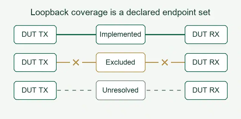
Quick Answer: A DUT external loopback PCB returns named DUT TX endpoints to named DUT RX endpoints in a defined fitted population and control state. Specify the links it implements or excludes and the elements in each path. Approve coverage against that record; a continuity result alone cannot establish that every required link is included.
Featured image: Conceptual coverage labels, not a wiring or switching instruction. Broken or dotted lines indicate disposition, not an implemented electrical path.
Before ordering the board, identify the version that will carry each requested loop. Fixed traces, fitted switches and AC-coupling components can produce different path expectations. Keep the intended coverage attached to the actual population so a familiar project name does not stand in for the released circuit.
Which endpoints does a DUT external loopback PCB connect?
A DUT external loopback PCB connects a transmitter endpoint of the device under test to a receiver endpoint of that device through a board-level path. Identify both ends from the customer’s released interface definition. The purchase scope should state whether the connection is fixed or depends on fitted components and control settings.
This object differs from a tester self-diagnostic loop, whose endpoints belong to the instrument. Calling both items “loopback boards” leaves the buyer without a usable circuit definition. Name the DUT interface and intended return path in the request.
Keep the device program and its functional coverage with the customer’s test owner. The manufacturing package supplies the released connections and construction to build; it does not determine which device behavior the program exercises.
Which endpoint pairs and exclusions belong in the release data?
List each required DUT link or lane, its TX endpoint, its RX endpoint and the applicable polarity. Mark whether that pair is implemented, deliberately excluded or awaiting a decision. Include unconnected required pairs in the review so the absence of a drawn loop cannot disappear from the purchasing record.
Use the endpoint identifiers from the released device and interface documents. Add the board population or topology identifier and the relevant fixed-path or control-state reference. A name such as “lane loop” leaves the actual endpoints and applicable configuration unspecified.
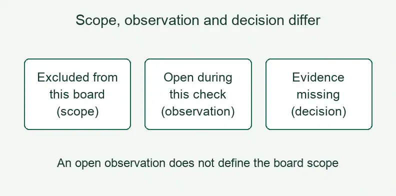
Keep coverage status separate from an electrical observation. “Excluded from this board” describes scope. “Open during this check” describes a result under stated conditions. “Evidence missing” describes an unresolved decision. Combining those entries into one “open” label can hide either an intentional exclusion or a missing required connection.
The existing probe-card guide covers the general PCB-netlist and channel-map distinction. Here, the added decision is which DUT loops the chosen board configuration includes and excludes.
Why does a continuity pass leave coverage questions open?
A continuity result concerns the connections checked under that method and configuration. Coverage also requires comparing the implemented paths with the complete requested endpoint set. A board can have correctly connected loops while leaving other required links unimplemented. Record those exclusions before accepting a result as evidence for the requested coverage.
Pavan Pakala’s 2011 Texas Tech University thesis documents a HyperTransport passive loopback DIB for a G34 package. It connects DUT transmitters to receivers on the board, bypassing the tester’s loopback cards. On printed page 27 (PDF page 37), the author reports checking the hard-wired connections with a multimeter while explicitly stating that the lower sublinks were connected and the upper sublinks were left open.
On printed page 36 (PDF page 46), the thesis states that production use would require connecting both lower and upper sublinks to test the complete link. The connected subset and the coverage gap existed together. This is one historical platform example, not a required pinout or a universal production-test method.
For your release, compare every requested pair with its implementation entry. Ask the test owner to approve a documented exclusion or identify the missing work. Retain any functional result against the covered subset and its actual configuration; do not extend it to absent loops.
How do control states change the endpoint pairs?
A control state can close one or several endpoint pairs. Give the complete configuration a stable identifier and list all pairs associated with it. As a buyer recommendation, retain the route identity if the same endpoints can use different routes. The customer owns the approved control definition and any restrictions on its use.
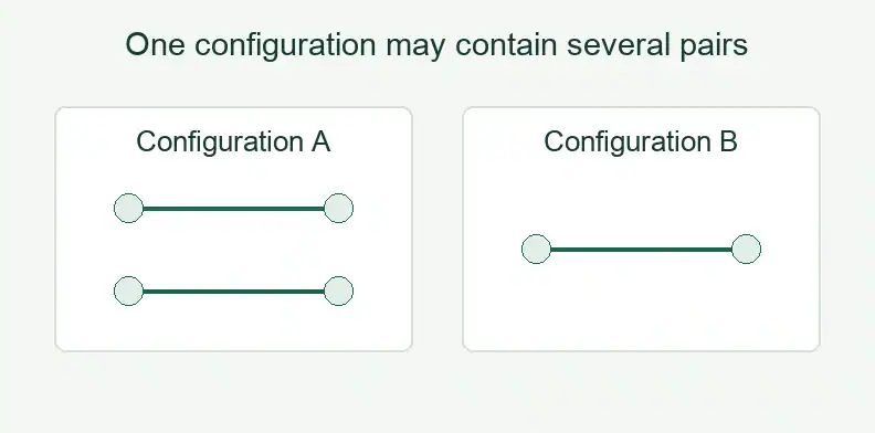
Stewart Yang of Menlo Microsystems and Jangwoo Lee of Advantest Korea illustrate this in their DesignCon 2023 loopback paper. Figure 11 presents six MM5620 configurations, including paths through AC-coupling capacitors and paths without them. Its truth table lists endpoint-pair relationships; some pairs share the same control setting. The nine pair rows are not nine independent configurations.
In the proposed release record, associate every pair with the complete customer-defined state ID. A single control-line value may be insufficient when other controls determine the route. Resolve missing control information with the circuit owner rather than treating it as an approved state.
Use state only as a key for the resulting endpoint set here. Control-transition sequences, timing and switching limits require their own approved requirements. The matrix below does not supply an operating procedure.
How do path contents change the expected DC result?
The expected DC result depends on what is fitted between the named endpoints and which path is selected. A series AC-coupling capacitor interrupts the intended steady DC connection through that branch. Record that expectation separately from functional signal transmission and check whether the actual circuit provides any alternative DC path.
A continuity beep cannot establish AC loop performance. A DC-open observation can be consistent with the intended AC-coupled route, but it needs interpretation against the circuit and measurement method. The test owner must specify the applicable check and limits; the word “loopback” supplies neither.
Population identity also changes what a result represents. On PDF page 20 (Figures 22–23), the Menlo/Advantest paper distinguishes an evaluation-board topology containing two MM5600 devices from another in which transmission lines replace those devices. Preserve that distinction when associating evidence with a board. A trace-only result does not establish the performance of the fitted-switch version.
Carry the actual BOM or controlled population identifier into the matrix. Record the selected route’s components without turning the record into a switch-selection, RF-launch or signal-integrity design guide.
What should the loop coverage and state matrix record?
Record the actual board population, requested DUT endpoint pair, applicable control state, path contents and coverage disposition together. Attach evidence and an approver to the relevant entry. The matrix should make deliberately excluded pairs and unresolved required pairs visible while keeping an expected DC observation separate from a customer functional result.
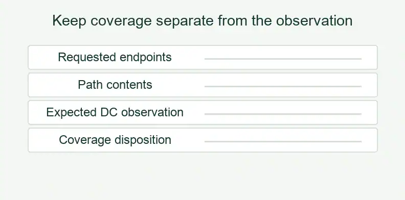
The following tool is an editor recommendation. Complete it from customer-approved interface and circuit records; it is not a standard or a record of measured results. Repeat the endpoint entry for each applicable configuration.
DUT loop coverage and state matrix
| Record field | Entry to provide |
|---|---|
| Actual hardware | Board PN/revision and fitted population or topology ID. |
| Requested coverage | DUT interface, link/lane and requirement reference. |
| Endpoints | TX endpoint, RX endpoint and released polarity definition. |
| Configuration | Fixed path or complete customer-approved control-state ID. |
| Path contents | Direct trace, series AC coupling, switch and other relevant fitted elements. |
| Coverage disposition | Implemented, deliberately excluded or unresolved; retain the requirement alongside it. |
| DC expectation | Expected result for this path and method, supplied by the test owner. |
| Evidence scope | Fabricated connection, assembled configuration or customer functional result; identify the covered pair/state. |
| Decision | Evidence reference, result, named approver and restriction or follow-up. |
For a state that closes several pairs, use the same state ID on each corresponding entry. Review the resulting set against the requested links. A blank entry remains unresolved until the responsible owner supplies a disposition.
Use the ATE PCB manufacturing page for the manufacturing inquiry. Agree which released fabrication or assembly data and inspection records belong in the order; device programming and functional coverage remain customer-owned.
What else should a loopback PCB buyer confirm? (FAQ)
Use these questions to resolve scope before ordering. The customer should identify the required DUT links, the actual board population and the owner of each coverage decision. Keep exceptions in the released record so a repeat purchase uses the intended endpoint set and configuration rather than an assumed equivalent.
Can the fabricator’s netlist test confirm all requested loops are covered?
It checks the supplied connections within the agreed method and scope. The customer must compare the implemented endpoint/state set with the requested DUT coverage and approve any exclusions.
Does an AC-coupled loop need to give a continuity beep?
No. Series AC coupling can interrupt the steady DC path. Interpret the observation using the actual circuit and the test owner’s method; a beep does not validate AC transmission.
Is a DUT loopback board the same as an instrument diagnostic kit?
The endpoints differ. This board returns DUT transmitters to DUT receivers. An instrument diagnostic kit connects instrument channels and needs its own configuration definition.
Can a loopback board intentionally leave some links unconnected?
Yes, if the customer approves the exclusion for the intended use. List the omitted links explicitly and restrict the coverage claim to the implemented subset.
Send your released files for a quote and free DFM review.
Send Gerber, drill data, stackup, drawings and netlist for a PCB quote. Include the approved endpoint/state matrix and the intended loop coverage.
For assembly, add the BOM and fitted-position data. Agree board checks; DUT programming and approval of loop coverage stay with your test team.