
Quick Answer: A burn-in board thermocouple record needs the channel identity, sensor construction, cold-junction compensation method and electrical connection conditions. Ask the test owner to approve that measurement chain and state what each channel may support, leaving any transfer to another temperature object unresolved until supported.
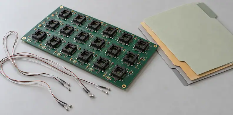
Featured image: Generic AI-generated illustration; not QueenEMS equipment or test data.
For a multi-channel burn-in board (BIB), a temperature log and the board drawing can reach different suppliers. Put channel identifiers and measurement-chain records in the handoff so the laboratory, test owner and board manufacturer work from the same released configuration.
What must each BIB temperature channel identify?
Give each channel a stable identifier and a named object in the released setup. A BIB record may contain the controller setpoint, chamber-air channel, marked PCB location, case or contact channel, or derived device junction temperature. Keep those identities attached to the records exchanged between the test owner, laboratory and board supplier.
For the broader reference-point and measured-versus-calculated discussion, use the existing temperature measurement reference guidance.
How does cold-junction compensation affect a thermocouple channel?
A thermocouple produces a voltage associated with its sensing junction and reference connections. Cold-junction compensation (CJC) uses the reference temperature to calculate the sensing-junction temperature. The compensation must account for the thermocouple’s nonlinear response in the voltage domain. Its sensing junction and a semiconductor device’s junction remain separate physical objects.
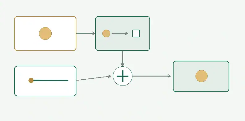
Joseph Wu’s TI guide to thermocouple measurements, revised March 2023, describes the conversion on pages 7–8 and 10. Convert the measured cold-junction temperature to its equivalent thermocouple voltage, add that voltage to the measured thermocouple voltage, then convert the sum to temperature using the appropriate thermocouple relationship. Adding two temperature values directly does not perform this compensation.
The reference measurement also has a physical location. TI states that the return connections of the different metals must share a known temperature. Additional metal junctions along the signal path can cancel in differential measurement when the corresponding pairs are at the same temperature. A temperature gradient can defeat that cancellation.
Ask the measurement provider to identify the reference block or connector, its temperature sensor and the compensation method used for the channel. If channels share a reference, record which channels use it. A label such as “CJC enabled” leaves those connections unidentified.
TI discusses an isothermal block and, for some implementations, copper around the reference connections. That guidance concerns the cold-junction measurement area. It supplies no prescription for making BIB device sites thermally uniform.
What should the test owner review about sensor construction and electrical contact?
The test owner should review sensor construction, attachment, electrical isolation and the acquisition circuit together. Exposed, grounded and ungrounded thermocouples differ in response and electrical contact. A probe touching a conductive part can connect that part to the measurement circuit. The channel record should identify who checked the resulting common-mode and ground-loop conditions.
TI describes an exposed junction as having direct heat transfer and a fast response. A grounded thermocouple joins the sensing element to its metal sheath. An ungrounded construction insulates the element from that sheath and responds more slowly in the guide’s comparison. Specify the chosen construction in the channel record so another laboratory can identify the same sensor arrangement.
For exposed or grounded probes, identify what the probe contacts electrically. TI warns that a contact potential different from the measurement ground can disrupt the circuit. Even matching ground potentials do not establish that the signal lies within the programmable gain amplifier’s common-mode input range. The acquisition-system owner must review the selected hardware and its device specifications.
Open-sensor detection needs a separate entry. TI describes resistor biasing and burn-out current sources that can make an open thermocouple produce a full-scale reading. That indication depends on the circuit; a full-scale reading alone does not distinguish an open sensor from a genuine high temperature.
The guide generally calls for a separate burn-out-current measurement because the diagnostic current can heat an intact sensor or create error voltage across input filter resistors. Filter capacitance also introduces settling requirements when changing between diagnostic and temperature measurements. Ask the provider to record the diagnostic method, its status during acquisition and the applicable settling basis. Do not insert a generic delay into the purchase specification.
What should a multi-channel BIB handoff contain?
Use a channel map to connect each temperature record to its sensor and released configuration, then use a separate handoff record to assign review and permitted use. The test owner approves measurement applicability; the laboratory supplies its acquisition details. The board manufacturer receives the released features and manufacturing requirements that concern the ordered build.
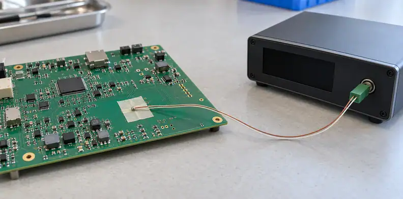
The two tools below are editor recommendations. They contain fields for the responsible parties to complete, with no default temperatures, tolerances or acceptance limits. Keep one map entry per channel and refer to supporting records by identifier.
Tool 1: Temperature-channel identity map
| Field | Entry to request |
|---|---|
| Channel and object | Channel/sensor ID and the named object represented by its result. |
| Physical identity | Marked location or object identifier, drawing reference and setup revision. |
| Sensor | Type, construction and test-owner-specified tolerance basis. |
| Reference | CJC reference identity, location and compensation-method record. |
| Attachment and electrical review | Attachment description, isolation/common-mode review record and responsible person. |
| Acquisition | Time-trace identifier, recorded conditions and acquisition/settling basis. |
Reuse a channel identifier consistently in the drawing, acquisition file and handoff. If the laboratory changes a probe or acquisition configuration, identify that configuration in the returned record. The buyer can then ask the test owner whether earlier applicability decisions still cover it.
Tool 2: Measurement-chain handoff and unresolved-transfer record
| Field | Entry to request |
|---|---|
| Covered channels | Channel-map entries and supporting measurement-record IDs. |
| Chain review | Sensor-to-acquisition configuration, CJC method and open-sensor diagnostic scope reviewed. |
| Recorded setup | Hardware revision and operating configuration associated with those records. |
| Permitted use | Material duty, device stress or setup only, as approved by the test owner. |
| Open transfer | From-object, to-object and missing evidence; derived Tj method and assumptions if applicable. |
| Disposition | Evidence provider, named approver, required follow-up and current restriction. |
“Unknown” is an available entry when the provider lacks the evidence. Material applicability is a separate decision that consumes an approved PCB-duty reference. Sensor calibration evidence also remains with the responsible measurement provider.
The ATE PCB manufacturing page covers the manufacturing inquiry. Include any required sensor-related board features in the released files and agree their inspection scope during quotation.
How should unresolved temperature transfers be recorded?
Record an unresolved transfer as a specific request for evidence: name the source object, intended destination object, missing support and person who must decide. Keep the restriction attached to the affected channels. The test owner can approve a supported use, request further work or retain the result for setup information only.
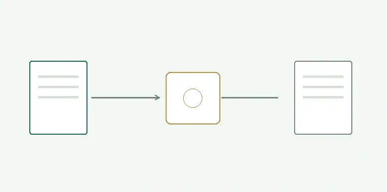
David L. Saums’ TestConX 2025 tutorial illustrates interface layers and reports case temperature in a particular comparison. Even for a comparable interface stack, that example supplies no default conversion from a case/contact reading to device junction temperature.
Request the supporting method and its applicable configuration before closing that entry. A completed drawing or a fabricated board cannot supply a missing device-temperature conversion.
What else should a BIB buyer confirm? (FAQ)
These buyer questions concern the measurement handoff. Put the chosen sensor, acquisition configuration and responsible reviewer into the project records before using a channel for an acceptance decision. Any missing information can remain an explicit open item with an owner, rather than becoming an assumed supplier deliverable.
Does enabling CJC establish the temperature of the device junction?
No. CJC compensates the thermocouple measurement for its reference connections. A derived device junction temperature requires the method and assumptions approved by the device or test owner.
Should every BIB thermocouple be ungrounded?
The test owner must choose for the application. TI describes response and isolation trade-offs; the review must include the contacted part and the acquisition circuit’s input requirements.
Can open-sensor detection run without affecting the temperature measurement?
That depends on the circuit. TI identifies possible error from burn-out current sources and settling between measurements. Request the diagnostic configuration and the provider’s acquisition basis.
Does the PCB quotation include sensor calibration or temperature correlation?
No. Keep those tasks with the customer or measurement provider. The QueenEMS inquiry concerns released manufacturing files and separately agreed assembly. Identify any required measurement work and its provider separately.
Send your released files for a quote and free DFM review.
Send Gerber, drill data, stackup and drawings for a PCB quote. Mark thermocouple-related features and the released channel references.
For assembly, add the BOM and thermocouple installation drawing. Agree the scope; calibration and temperature correlation stay with the measurement owner.