
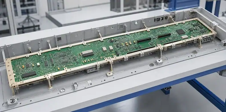
Quick Answer: A large PCB stiffener should carry connector, component and service loads into the chassis without forcing the laminate flat. Select rails, frames, backing plates or local brackets from the actual load path, support span and access needs. Board thickness helps stiffness, but it does not replace a mechanical support review for a long board with concentrated loads.
A large rigid PCB can pass fabrication flatness inspection and still deflect when a connector is mated, a heat sink is installed or a technician presses near the middle of an unsupported bay. Adding metal at the end of layout is not a controlled fix. Large PCB stiffener design starts by identifying forces, reactions and allowed board movement before mounting holes and keep-outs are frozen.
This page addresses external mechanical reinforcement. Laminate symmetry, copper balance and fabrication behavior remain covered by large PCB warpage control, while broad layout preparation belongs to large PCB design rules.
Table of Contents
- Decide whether the board needs reinforcement
- Draw the load path before choosing hardware
- Compare rails, frames, plates and brackets
- Place mounting points and electrical keep-outs
- Avoid over-constraint and thermal stress
- Preserve assembly, inspection and test access
- Validate the support on a first article
- Prepare a stiffener-ready RFQ
- Assign structural release ownership
Decide whether the board needs reinforcement
A stiffener is justified when board deflection or stress under a defined load can threaten fit, solder joints, components, connectors or service operation. Outline alone is not the decision. Span, thickness, mounting layout, mass distribution and applied forces determine whether the chassis already provides adequate support.
Separate static sag from operating loads
Static sag comes from the board and component mass between supports. Operating loads come from connector insertion, switches, card guides, cable pull, heat-sink fasteners, shock, vibration and maintenance. A board that appears stable on a flat inspection table may bend sharply when a rear-panel connector is mated.
List each load with direction, point or area of application, expected frequency and reaction point. This turns “the board feels flexible” into a mechanical problem that a designer can analyze, fixture and test.
Use thickness as one variable, not the answer
Increasing finished thickness can raise board stiffness, but it also changes material consumption, connector compatibility, drilling/plating route and assembly mass. The PCB thickness selection criteria should be reviewed with stack-up and fabrication limits before treating a thicker board as a mechanical shortcut.
A local connector load may still need support directly beneath the connector even when the overall laminate is thicker. Conversely, a well-supported chassis can make a large outline viable without adding a heavy plate.
Decision point: Specify a stiffener only against a named load case and allowable mechanical outcome, not because the outline is described as large.
Draw the load path before choosing hardware
The best support path carries force from the loaded feature into a frame, enclosure or mounting structure over the shortest practical distance. A long aluminum bar at an unrelated edge may add mass without reducing strain where the board actually bends.
React connector and service forces locally
Panel connectors, press-fit connectors and frequently serviced interfaces deserve their own reaction path. Put mounting or backing support close enough that mating force travels through hardware rather than across a wide laminate span. Use the drawing and allowable loads for the exact connector. The Hirose FH75M-120S-0.4SH(05) drawing is an FPC/FFC connector-specific example; it does not specify a general-purpose metal stiffener for large rigid PCBs.
For a connector at the end of a long board, consider whether the stiffener locates the connector or merely supports the board. Those functions need different tolerances. The connector may reference the enclosure while the PCB uses clearance around secondary mounts to avoid forced alignment.
Support heavy components without loading solder joints
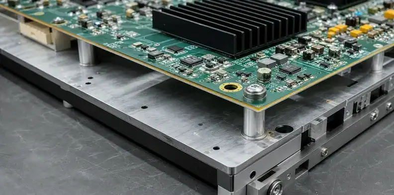
Transformers, inductors, heat sinks and shielded modules should transfer mechanical load through their intended fasteners or support features. A backing plate can react a fastener, but it must clear bottom-side pads, vias, solder joints and component leads. Insulating washers or spacers need controlled material, thickness and compression.
The component mass map belongs in the cross-functional feasibility review because assembly handling and final chassis support may require different contact zones.
Load-path rule: A stiffener earns its place when the force enters and leaves through defined features without using solder joints or unsupported laminate as the structural member.
Compare rails, frames, plates and brackets
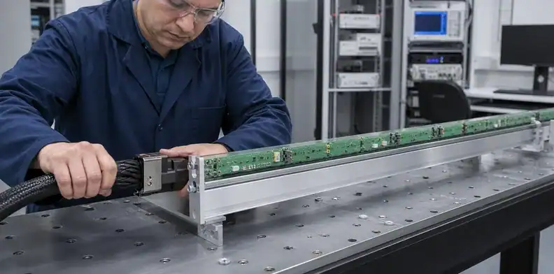
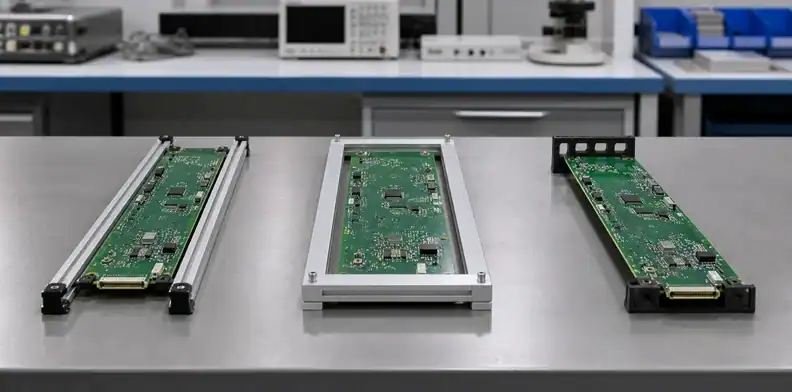
Support architecture should match the direction and location of the dominant load. One design may use several types rather than a single universal bar.
Match support type to the load path
| Architecture | Best use | Main design risk | Evidence to request |
|---|---|---|---|
| Edge rail | Long straight span with clear edge | Rail twists or blocks conveyor/tooling edge | Rail section, attachment pitch, deflection check |
| Perimeter frame | Ring or open-center board | Frame tolerance forces the board shape | Datum scheme and floating-point details |
| Backing plate | Distributed support and heavy zones | Heat trapping or bottom-side interference | Pocket map, material and thermal review |
| Local bracket | Connector, switch or heat-sink reaction | Point load near copper/features | Hardware stack and keep-out drawing |
| Chassis standoffs | Existing enclosure support grid | Excess span between sparse mounts | Standoff map and board deflection test |
Edge rails are efficient when the rail lies near the bending axis and can attach at a useful pitch. A backing plate offers more continuous support but may interfere with airflow, bottom-side inspection, rework and test probes. Perimeter frames suit unusual shapes, while local brackets avoid reinforcing regions that do not need it.
Check mass, material and lifecycle constraints
Do not copy a stiffener material or thickness from another product without matching span and load. The same aluminum extrusion behaves differently when its mounting pitch doubles or its weak axis is rotated.
Mass and service access often decide between a plate and discrete rails. A portable product may not tolerate the plate weight, while a stationary control assembly may value the plate as a shared support for several heavy devices. Where the backing member also conducts heat, keep the thermal interface and structural interface as separately controlled features; changing a pad thickness should not unknowingly change fastener preload.
Corrosion and finish compatibility also belong in the material choice. Dissimilar metals, conductive debris and unfinished cut edges can create product risks that a simple stiffness comparison misses. Specify surface finish, isolation hardware, cleaning state and whether the stiffener is installed before or after final wash.
Place mounting points and electrical keep-outs
Mounting points should reduce unsupported bays while respecting high-voltage spacing, copper keep-outs, signal return paths and manufacturing tolerance. Hardware is part of the electrical and mechanical design, not a late enclosure detail.
Use functional datums and a restraint strategy
Choose one primary locating feature, one secondary feature that controls rotation and remaining mounts that permit tolerance. Round holes on every stiffener point can over-constrain a long board if the frame and PCB hole patterns accumulate differently. A slot or clearance feature may be appropriate at a non-datum mount when engineering approves the movement direction.
Dimension connector-to-chassis relationships from functional datums. The PCB hole-position datum controls help keep fabrication inspection aligned with the mechanical assembly that will use the holes.
Keep metal and fasteners away from electrical hazards
Define copper, via, component and solder-mask keep-outs around screws, rivets, spacers and conductive stiffeners. Account for washer diameter, installation tool access, tolerance and possible rotation. A nominal screw centerline is not a complete clearance definition.
Metal close to antennas, high-speed channels or high-voltage circuits may change electrical behavior. Ask electrical engineering to approve the final stiffener STEP model, not only a 2D mounting-hole pattern.
Evidence check: Freeze holes only after the datum owner, clearance envelope and permitted movement at every non-primary mount are documented.
Avoid over-constraint and thermal stress
A stiffener should support the board in its acceptable natural condition, not flatten it by assembly force. Pulling a board against a twisted frame can store strain that reappears around solder joints, connectors or plated holes.
Measure the board and frame using the same datum logic before blaming one part. Define whether shims are permitted, who selects them and whether they are permanent controlled parts. Informal washers added on the assembly floor can change screw engagement, connector height and electrical clearance.
Materials also expand differently with temperature. A long metal rail and an FR-4 board may change length by different amounts as the product warms. Fixed attachment at every hole can transfer that difference into the laminate. A defined primary anchor plus controlled sliding or clearance points can reduce restraint, provided vibration and connector alignment remain acceptable. For an illustrative free-expansion estimate, assume a mount 500 mm from the primary datum, a 60 K temperature change and a difference in expansion coefficients of 8 micrometres/(metre K). Relative movement is 0.500 x 60 x 8 = 240 micrometres, or 0.24 mm. These are hypothetical inputs, not material specifications or a required slot length. Use the actual directional laminate and frame data, temperature range, tolerances and restrained-load model to set permitted movement.
For a design that needs help selecting contact points, submit the board STEP model, chassis model, load directions and temperature range through the QueenEMS DFM review process. The result should be a list of conflicts and fabrication/assembly questions; final structural approval remains with the product’s mechanical engineering owner.
In practice: Do not use fastener torque to make an out-of-tolerance board or frame appear dimensionally correct.
Preserve assembly, inspection and test access
Mechanical support can solve one problem and block three production operations. Review the stiffener in the same orientation used for printing, placement, reflow, AOI, rework, electrical test and final enclosure assembly.
| Process | Access the support must preserve | Common conflict |
|---|---|---|
| SMT printing | Edge clamp, underside support, fiducials | Rail covers printer clamp zone |
| Placement | Nozzle and camera field | Bracket shadows a local fiducial |
| Reflow | Conveyor clearance and airflow | Plate adds unprofiled thermal mass |
| AOI/X-ray | Inspection field and board positioning | Frame blocks view or machine grip |
| ICT/FCT | Probe points and counter-support | Backer occupies support/probe locations |
| Service | Tool path and replaceable modules | Fastener hidden beneath components |
Temporary process carriers and final product stiffeners may be different tools. Do not assume a product backing plate can travel through reflow unless material, clearance and profile are qualified. Likewise, do not leave a production carrier attached in the final product without a product-level mechanical and environmental review.
The large PCB assembly equipment path identifies the machine interfaces that must be checked before stiffener geometry becomes fixed.
Access check: Release the support design only after every required process has a named grip, datum, clearance and removal state.
Validate the support on a first article
Validation should reproduce the loads that justified the stiffener. Measure board deflection or strain at relevant zones while connectors are mated, fasteners are torqued, heavy modules are installed and service operations are performed. A photograph of an assembled bar proves presence, not mechanical performance.
Use a first-article stack that includes the actual board revision, hardware, spacers, frame and torque method. Record free-state board condition before assembly, assembled condition and the result after load removal. Inspect nearby solder joints, press-fit zones, ceramic components and plated holes when the load path passes through them.
Acceptance criteria must come from product engineering. When no universal deflection value is appropriate, define functional checks: connector alignment, enclosure fit, no contact with prohibited features, no permanent set beyond the drawing requirement and repeatable assembly without forcing parts.
Repeat the check after transport and thermal exposure when those conditions can loosen hardware or change the interface. Witness marks on washers, changed connector alignment or a gap beneath one support can reveal load redistribution that was absent during initial assembly. Record torque verification separately from structural acceptance; a fastener can retain torque while the supported stack settles.
Changes to rail section, attachment pitch, plate pockets, fasteners or chassis datums require controlled review. A “minor” machining change can relocate stiffness and create a new high-strain region.
Prepare a stiffener-ready RFQ
The mechanical package should let the PCB supplier, assembler and enclosure team review the same structure.
| RFQ input group | Minimum content |
|---|---|
| PCB definition | Gerber/ODB++, drill, fabrication drawing, finished thickness, stack-up and board mass |
| Mechanical definition | Board/enclosure STEP models, common datums, component mass/height map and bottom-side keep-outs |
| Applied loads | Connector insertion, cable, fastener and service-load directions |
| Stiffener definition | Material, finish, electrical isolation, hardware stack, torque method and permitted floating mounts |
| Verification | Mechanical test, dimensional report and first-article quantity |
Send this package through the QueenEMS large PCB quotation route. QueenEMS can review whether the proposed mounts, keep-outs and process access are compatible with the PCB/assembly route and return quotation assumptions or DFM questions. To request that review, send the stiffener and chassis files to QueenEMS and name the load cases that must remain controlled.
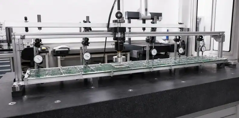
Assign structural release ownership
The PCB fabricator can confirm board construction, the assembler can review access and handling, and the stiffener supplier can control the mechanical drawing. None of those parties automatically owns the finished product’s structural safety. Name the engineer who approves load cases, permissible deflection, fastener behavior and enclosure interaction, then record which supplier evidence supports that decision.
Release rule: A quotation can confirm manufacturability, but the product owner must approve structural loads, deflection and final chassis safety before the support design is released.
FAQ
Does every large PCB need a metal stiffener?
No. A board with short supported spans and low applied loads may use chassis standoffs alone. Add a stiffener only when analysis or testing shows that the defined mechanical outcome needs more support.
Is a thicker PCB better than a stiffener?
Not automatically. Greater thickness affects the complete fabrication and connector system, while a stiffener can target a local load. Compare both choices against stack-up, mass, support span, access and cost.
Can an aluminum plate touch the PCB directly?
Only at approved contact areas with electrical clearance, surface compatibility and tolerance defined. Use controlled spacers or insulating hardware where required; never let the plate rest on solder joints or components.
Should every mounting hole tightly locate the board?
No. A long board often needs a primary/secondary datum strategy plus clearance or controlled movement at other mounts. Tight location at every hole can force tolerance and thermal mismatch into the laminate.
What evidence should accompany the first article?
Request the as-built hardware stack, dimensional results, free and assembled board condition, load-test setup, connector-fit result and photographs of all approved contact points.
Sources
- PICMG COM-HPC Carrier Design Guide Rev. 2.1 (COM-HPC implementation guidance; not a general stiffener specification)
- Hirose FH75M-120S-0.4SH(05) FPC/FFC connector drawing (part-specific)
Written by the QueenEMS Engineering Team
Upload your files today · Free DFM check before production · Ship worldwide
Get your PCB prototypes in as fast as 24 hours. We handle FR4, Rogers, and hybrid boards up to 40 layers in volume production, with advanced builds subject to engineering review — free prototypes for 2–4 layer FR-4 boards, no minimum order.
Just upload your Gerber + BOM — we source every part, assemble, and inspect (AOI + X‑Ray) so you don't have to chase suppliers. Boards ship in as fast as 24 hours.