
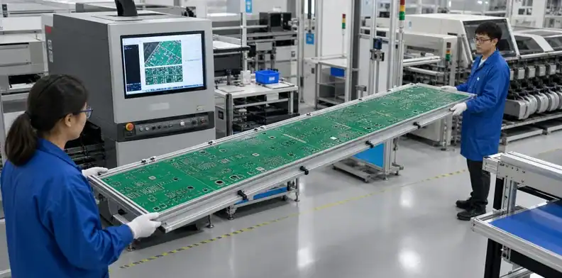
Quick Answer: Large PCB handling needs a support method that carries the board across its full span instead of treating the laminate as its own tray. Define approved hand-contact zones, carrier support, storage orientation and transfer inspection before the first board moves between fabrication, inspection and assembly. ESD, moisture and cleanliness controls remain necessary, but none of them prevents a long board from bending under its own mass.
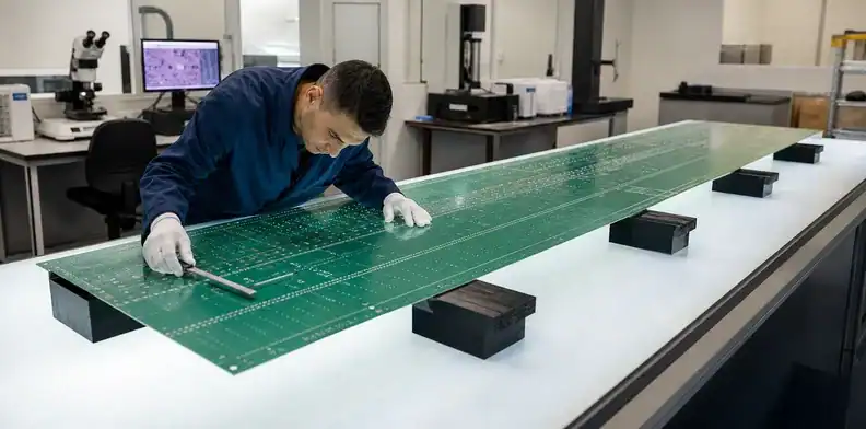
A board can leave electrical test flat and arrive at the SMT printer with a new bow, scratched finish or strained connector area. The damage often occurs during an ordinary transfer: one operator lifts a corner, a board bridges two rack rails, or a populated assembly is stacked while another station becomes available. Large PCB handling turns these informal movements into a controlled production route.
This article addresses work-in-process movement inside manufacturing and assembly. Outbound transport belongs to a separate oversized PCB packaging plan, while laminate balance and process-induced distortion belong to large PCB warpage control.
Table of Contents
- Separate the four handling risks
- Choose approved contact and lift zones
- Make the carrier support the board
- Control carts, racks and temporary storage
- Protect bare boards and populated assemblies
- Inspect every handoff
- Validate the full handling route
- Send a handling-ready RFQ package
Separate the four handling risks
Large PCB handling must control mechanical strain, surface contamination, electrostatic discharge and moisture as four related but different risks. An antistatic bag can protect against charge and still allow a thin board to sag. A rigid tray can carry the span and still contaminate ENIG contacts if its surface is dirty.
Bare-board risk starts at the finish and unsupported span
Bare boards expose solderable finishes, edge contacts, plated holes and routed features before the assembly process adds mechanical mass. Finger contact can leave residue on a finish; sliding across a bench can scratch solder mask or burr an edge. On a long outline, the larger immediate concern is often bending while the operator changes grip.
The released drawing should mark functional edges, connector bevels, press-fit areas and any keep-clear surface. These markings do more than guide final inspection. They tell the handling designer where a tray lip, slot divider or gloved hand may not touch.
Populated boards add concentrated mass
A PCBA no longer behaves like a uniform plate. Transformers, heat sinks, long connectors and shield cans move the center of gravity and create local load paths. Lifting at two convenient corners may twist the board around a heavy component even when the bare board felt stiff.
Component keep-outs must therefore appear on the handling drawing as three-dimensional volumes. A carrier that worked during bare-board inspection may contact bottom-side components after assembly or push against a solder joint during storage.
Evidence check: ESD compliance does not approve a carrier mechanically; the support surface and contact zones require a separate engineering review.
Choose approved contact and lift zones
Operators should lift a large PCB only from structural zones identified by the product and process teams. “Handle by the edges” is incomplete when the edge contains gold fingers, a bevel, fragile routed tabs or a long unsupported bay.
Manual movement needs a repeatable grip
Mark two-person lift points or fixture pickup points directly on the work instruction. The grip should keep the board near its supported orientation and avoid switching hands over components. For a populated board, the instruction also needs a safe tilt limit so tall or heavy parts do not turn a horizontal lift into an unplanned cantilever.
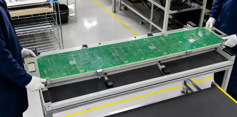
Where the outline is too wide for a neutral manual grip, move the carrier rather than the PCB. Handles belong on the carrier outside the component envelope. This lets the operator transfer one controlled object without touching the laminate.
Contact zones must follow the next process
A rail used for optical inspection might cover an SMT conveyor edge. A tray boss aligned under a bare-board laminate area might interfere with a bottom-side component fitted later. Define the carrier state by operation: bare board, printed board, placed board, reflowed assembly or tested product.
The large format PCB assembly route helps identify which edge rails, tooling holes and travel orientation each station needs. Handling hardware should preserve those same references rather than creating another datum system.
Decision point: When a neutral two-hand or two-person grip cannot keep the span supported, the work instruction should require carrier-based movement.
Make the carrier support the board
A full-span carrier should transfer bending load through a rigid support plane, not through distant points on the PCB. The support pattern must clear functional surfaces and components while remaining close enough to prevent visible sag during acceleration, stopping and workstation loading.
| Carrier input | What engineering defines | Why it changes the design |
|---|---|---|
| Board outline and thickness | Released dimensions and tolerance | Sets pocket size and unsupported span |
| Mass and center of gravity | Bare and populated conditions | Controls handle position and tray stiffness |
| Approved contact map | Neutral laminate and rail zones | Prevents finish or component contact |
| Bottom-side envelope | Component height and keep-outs | Defines pockets, standoffs and clearance |
| Station interfaces | Conveyor, bench, AOI and test datums | Keeps one orientation through the route |
| Storage duration | Minutes, shifts or longer holds | Changes moisture barrier and support needs |
The useful design output is a carrier drawing with support height, pocket clearance, retainers, handles and identification—not a note that says only “use a tray.”
Retainers should stop sliding without forcing the board against a hard wall. Allow board-outline tolerance, thermal change and normal loading variation. Foam or soft materials require compatibility review: they may shed particles, retain moisture, charge differently or compress until a component takes the load.
Control carts, racks and temporary storage
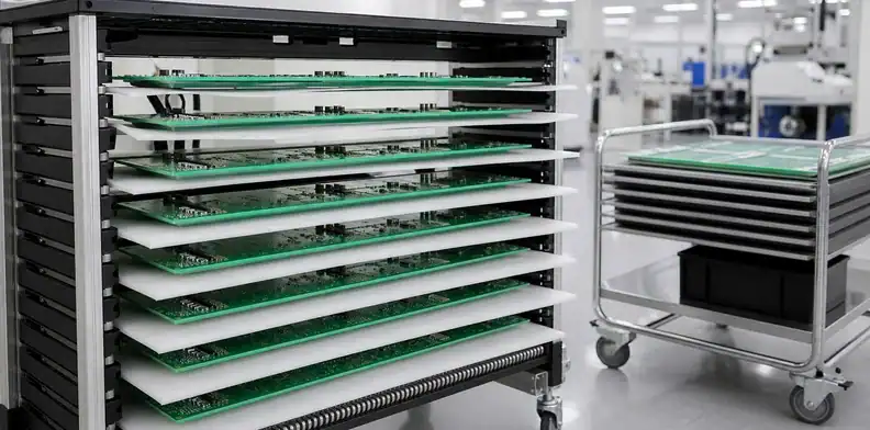
Temporary storage must preserve the same support condition used during movement. A board that lies flat on a tray during transport can still sag when the tray is removed and the board is placed across two rack rails.
Choose storage orientation from the support map
Horizontal storage works when a rigid tray supports the complete active span and protects bottom-side features. Vertical storage can reduce footprint, but the slot contact must be wide, clean and located on an approved edge; the board cannot lean against components or flex between narrow dividers. The correct orientation follows the board’s mass map and contact restrictions, not a universal rule.
Never stack populated boards directly. Even bare boards need controlled separators and a stated quantity when stacking is part of an approved method. The top board’s weight, separator location and particles trapped between surfaces all change the result.
Control cart motion, queues and orientation
Cart acceleration and floor joints also matter. Retainers should keep trays seated without clamping the PCB, and casters should not send repeated shock through an unsupported span. Assign each carrier a load direction so operators do not rotate it merely to fit a narrow aisle.
Queue management belongs in the traveler as well. State the maximum number of carriers per cart, whether empty carriers may be nested with loaded ones, and how a partly completed lot is separated from accepted output. A “temporary” bench position can last an entire shift when a machine stops, so the approved support and environmental condition must remain valid during an interruption.
Label orientation on both the carrier and rack. The operator should be able to confirm board side, travel direction and protected edge before removing restraints. Color alone is insufficient where lighting, cleaning or color-vision differences can create ambiguity; use a part/revision mark and a clear physical arrow.
Storage rule: A rack position is approved only when it supports the carrier or the designated PCB zones without creating a new span.
Protect bare boards and populated assemblies
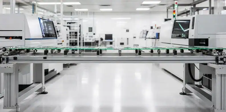
Mechanical support, ESD control, moisture control and cleanliness must be combined according to the board’s current state. IPC-1601A treats handling and storage as a route from bare-board manufacture through assembly; the practical lesson is that one packaging material cannot cover every risk.
Bare-board operators need clean gloves or approved handling tools, protected solderable surfaces and a method that avoids rubbing boards together. Assemblies with ESD-sensitive devices add grounded workstations, dissipative carriers and verified operator controls. Moisture-sensitive components may add sealed storage and exposure-time records after the moisture barrier is opened.
Do not place a flexible moisture bag beneath a long board and assume it is a tray. Put the barrier system around a mechanically supported configuration. Likewise, a conductive rack is not automatically safe if its narrow slots point-load the board.
At the first contextual review point, send the outline, thickness, bare/populated mass and underside component map through the QueenEMS DFM review path. The useful return is a list of acceptable contact and support zones that can be incorporated into carrier and station instructions.
Process call: Add environmental controls around the qualified support method; never substitute them for that support method.
Inspect every handoff
Each station should accept the board in a named condition and record damage before changing the carrier, orientation or restraints. This prevents a scratch found after AOI from becoming an argument among fabrication, assembly and test.
| Handoff check | Bare board | Populated board | Stop condition |
|---|---|---|---|
| Carrier identity | Correct part/revision | Correct part/revision | Wrong or damaged carrier |
| Support/contact | Approved zones only | Clears all components | Board resting on a feature |
| Surface condition | Finish, mask, edges | Components, joints, connectors | New damage or contamination |
| Shape | Agreed support and method | Agreed support and method | Visible change or failed criterion |
| Traceability | Lot and traveler | Assembly serial/lot | Identity cannot be reconciled |
Photographs are useful when they show the board in the carrier before unloading, not only a close-up after evidence has been disturbed. Record the station, time, orientation and carrier ID with any abnormality.
For a measured shape issue, use the same datum and support method defined in the large PCB inspection plan. An unsupported photograph cannot separate true board deformation from gravity sag.
Handoff trigger: Quarantine the unit when its support condition or visible state differs from the incoming record; do not carry uncertain damage into the next operation.
Validate the full handling route
Run one representative board through every manual and automated transfer before approving the production traveler. Include incoming inspection, temporary queue positions, printer loading, placement, reflow exit, AOI, rework, test and final pack-out. A route that looks safe at a bench may fail at the narrowest cart, highest rack or deepest bottom-side component.
Observe how operators actually grip the carrier, whether handles clear guards, whether the tray sits flat at each station and whether the board changes orientation. Check carrier deflection under the populated mass rather than testing an empty tool. Mark any station that requires the PCB to leave its primary support and design a local fixture for that transition. For a populated assembly with strain-sensitive packages, use NI’s strain-gauge measurement guidance to plan a timed handling trial where the product reliability plan calls for strain measurement. Synchronize the gauge record with carrier pickup, cart transfer, rack insertion and the moment the board leaves its support. This identifies a short loading event that a before-and-after flatness check can miss. Document gauge positions and orientations, the board revision and the actual handling sequence; use product-approved limits rather than a generic microstrain number.
Acceptance evidence can include before/after shape measurements under the agreed support condition, photographs of contact zones, carrier inspection, surface checks and confirmation that no component or solder joint carried handling load. The PCB board thickness selection may inform stiffness, but thickness alone should not be used to waive route validation.
Send a handling-ready RFQ package
A useful large PCB handling quotation needs the exact physical and process conditions, not only length and width. Include:
- Released board outline, thickness and tolerance
- Bare-board and populated mass, plus major component locations
- STEP model or underside height map
- Protected finishes, connector edges and no-contact regions
- Planned station sequence and travel orientation
- Maximum temporary storage duration and environmental state
- Required carrier quantity, identification and cleaning method
- Incoming/handoff inspection and quarantine expectations
Send these inputs with fabrication and assembly quantities through the QueenEMS large format PCB review. QueenEMS can use the package to review the board’s process route, identify carrier/contact questions and prepare a quotation with the handling assumptions visible. For a formal request, submit the handling package to QueenEMS and ask for the approved support condition to be listed with the quote.
Quotation boundary: Do not release tooling or production until the quote, carrier drawing and work instruction identify the same board revision and handling state.
FAQ
Can operators handle a large PCB only by its edges?
No. Edge contact is safe only when those edges are structurally suitable, free of protected finishes and supported well enough to avoid bending. A long or populated board may require a full-span carrier even when gloves and ESD controls are correct.
Should a large PCB be stored horizontally or vertically?
Choose the orientation from the approved support map. Horizontal storage needs a rigid, flat carrier; vertical storage needs broad clean slot contact on permitted edges and must not let the board lean on components.
Can antistatic foam support the board?
Only after material, cleanliness, compression and contact compatibility are reviewed. Foam can be part of a carrier, but it should not become an undefined structural support or touch sensitive finishes and components by convenience.
How do I know whether two people are required?
Use board size, populated mass, center of gravity, approved grip spacing and the ability to keep the board in its supported orientation. When one operator must change grip or allow the span to sag, require two-person or carrier-based movement.
What should receiving photograph?
Photograph the unopened carrier state, restraints, board orientation, contact zones and any damage before unloading. Keep the carrier ID, lot/serial identity and station handoff with the images.
Sources
- IPC-1601A Printed Board Handling and Storage Guidelines — table of contents and scope
- IPC technical resource on manual product handling
Written by the QueenEMS Engineering Team
Upload your files today · Free DFM check before production · Ship worldwide
Get your PCB prototypes in as fast as 24 hours. We handle FR4, Rogers, and hybrid boards up to 40 layers in volume production, with advanced builds subject to engineering review — free prototypes for 2–4 layer FR-4 boards, no minimum order.
Just upload your Gerber + BOM — we source every part, assemble, and inspect (AOI + X‑Ray) so you don't have to chase suppliers. Boards ship in as fast as 24 hours.