
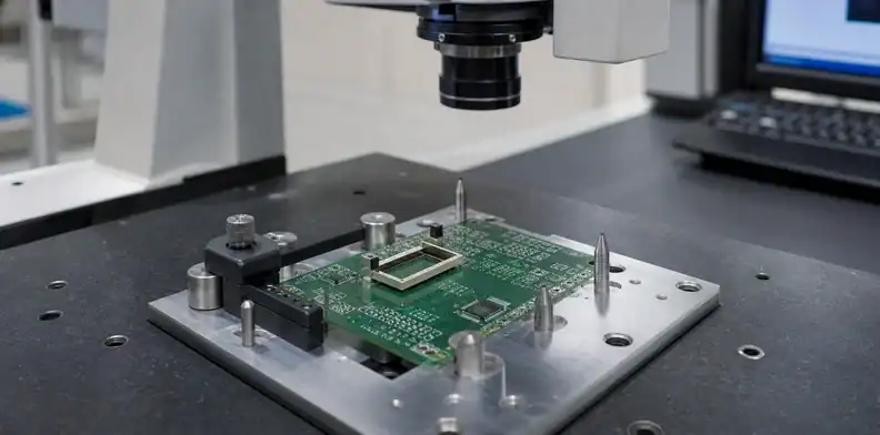
Quick Answer: A finished-hole size does not define where the hole pattern must land. Critical connector, enclosure, fixture, and press-fit holes need a drawing datum scheme, a position requirement, and a stated measurement method. Use the drill file for nominal coordinates, then use the fabrication drawing to state which relationships control acceptance.
Key takeaways
- Hole size and hole location are different requirements.
- Datums should match the mechanical assembly, not a convenient CAD origin.
- A critical pattern needs measured evidence before a fit failure becomes a claim.
A PCB can have every hole drilled to the correct finished diameter and still miss a connector shell or enclosure boss. The gap is usually a missing datum relationship. A drill table gives nominal locations; it does not tell CAM, inspection, or purchasing which two holes establish the product coordinate system or which pattern can tolerate panel movement.
For context only, IPC-6012EA section 3.4.1, an automotive addendum to IPC-6012E, states minimum hole and copper-pattern feature location accuracy of ±0.075 mm up to 300 mm, ±0.112 mm up to 450 mm, and ±0.150 mm up to 600 mm. The same section states a ±100 µm finished-hole-size tolerance. These are requirements of that named automotive addendum, not universal RFQ defaults; the applicable contract, board construction, and functional datum relationship govern this board.
Table of Contents
- Find the holes that locate the assembly
- Build a datum scheme from the mating part
- Separate diameter from position
- Control pattern relationships
- Account for fabrication movement
- Choose evidence that matches risk
- Inspect with the mating condition
- Package the RFQ
- Turn a critical drill pattern into a measurable assembly requirement
Find the holes that locate the assembly
Mounting features, shield pins, card-edge hardware, press-fit arrays, and fixture holes deserve a separate critical-hole list. A simple clearance screw that has generous play should not receive the same control as a connector pattern that must meet a molded housing.
Begin by classifying the pattern by its mating job. A USB or board-to-board connector shell, a shield can, a press-fit connector, and a test fixture all locate the product differently. The drawing should flag the holes whose centers govern fit, rather than forcing a tight location demand on every drill hit. This focuses cost and measurement effort on the positions that can create an assembly failure.
Datum rule: The locating pattern must use references that exist on the assembled product.
Build a datum scheme from the mating part
Choose primary, secondary, and tertiary references from the enclosure, connector, or test fixture geometry. The board outline can be a poor datum when routing tolerance is not the real functional relationship. A named datum set lets design, CAM, and incoming inspection discuss the same origin.
The strongest datum scheme comes from the physical assembly. A primary board face may establish seating, a side edge or locator may establish rotation, and a second feature may constrain lateral movement. A CAD origin that is convenient for layout can be unsuitable when the finished outline is not the reference used by the housing. Show datum symbols in the mechanical view where inspection can reproduce them.
Position rule: Keep finished-hole size and hole-axis location as separate controlled requirements.
Separate diameter from position
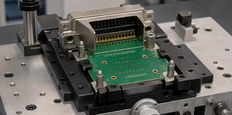
State the finished-hole requirement in the drill table and the location relationship in the mechanical drawing. Avoid a note that calls every coordinate a tolerance without saying whether it applies to hole center, plated wall, finished diameter, or the whole pattern.
Finished diameter and true position answer different questions. The drill table can control the plated or non-plated finished size, while the drawing states where the hole axis must land relative to its datums. If an array has unequal pitch, identify which pitch and which overall span are functional. Otherwise, individual coordinate checks can pass while the mating connector still refuses to seat.
| Situation | Preferred treatment | Drawing fields that matter |
|---|---|---|
| Connector shell | Mating face and locator holes | Pattern position and first-article fit |
| Press-fit array | Connector datum | Finished diameter plus location report |
| Enclosure screw | Housing datum | Functional clearance or position |
| Tooling feature | Fixture interface | Location relative to inspection datum |
Control pattern relationships
A connector may tolerate movement relative to the board outline but not relative to another connector or an optical aperture. Dimension the relationship that drives assembly. This keeps a supplier from satisfying each independent coordinate while the combined pattern no longer mates.
Consider the entire location chain: drill registration, plating growth for the finished hole, panel handling, profile routing, and the mating-part tolerance. The right limit is the one that leaves enough clearance after those contributors are combined. Requiring a very small coordinate tolerance without a functional analysis may only trigger a quote exception; it does not automatically make the connector fit better.
Measurement rule: A location report is valid only when its datum setup is stated.
Account for fabrication movement
Drilling, plating, imaging, routing, and panel handling all create practical variation. The right response is not an arbitrary ultra-tight note; it is a controlled requirement tied to the function and a supplier confirmation that the stated build can meet it.
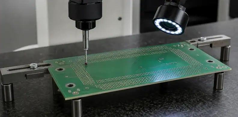
Measurement should use a repeatable setup. An optical system can report centers from reference features, whereas a fixture with locating pins can reveal the functional fit directly. For a high-risk pattern, ask how the reference is established before ordering a report. A list of X and Y values is weak evidence if the supplier and buyer used different zero points or different outline edges.
The related press-fit hole tolerance article addresses press-fit hole size; it should be paired with, not substituted for, the datum-controlled location requirement.
Choose evidence that matches risk
Optical measurement can be useful for many patterns, while a CMM or fit gauge may be justified for a critical mechanical interface. Request a first-article result when the relationship is new, then decide whether repeat lots need a certificate, a sample check, or no additional report.
The automotive IPC-6012EA values cited above are an example of a specific document, not a default tolerance to paste onto commercial boards. Contract class, finished size, board span, and mating clearance need to be reviewed together. When a customer drawing specifies a tighter condition, request a capability discussion before release rather than treating the standard table as an automatic acceptance override.
| Hole-pattern check | Evidence | Decision owner |
|---|---|---|
| Assembly datum scheme | Dimensioned datum view | Mechanical design |
| Finished hole condition | Drill table and plating callout | PCB engineering |
| Connector pattern location | CMM, optical, or gauge result | Quality engineering |
| Housing fit | First-article assembly result | Product owner |
Tolerance rule: Set the limit from mating clearance, not from a copied coordinate note.
Inspect with the mating condition
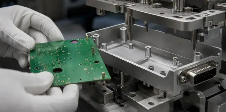
Receiving should not only measure one hole in isolation. Use the released datum and, where possible, the connector shell, enclosure, or fixture that exposes the functional relationship. Keep any failed sample unchanged until its location evidence is captured.
A first-article check should test the relationship that fails in real use. Mount the connector shell, housing boss, press-fit block, or fixture plate using the stated datums, then retain the measured result if it is a new build. Do not discard a failed sample before photographing the datum setup and identifying the board revision; that evidence helps distinguish a design tolerance issue from a process escape.
Review the critical pattern against annular-ring breakout acceptance when annular-ring margin and positional evidence meet at the same hole.
Package the RFQ
Send the released drill data, fabrication drawing, datum view, critical-hole list, mating CAD or drawing, board outline, and desired first-article evidence. QueenEMS can return the hole-position questions before the job is quoted as an ordinary drilled board.
A complete RFQ includes the drill file, board outline, datum drawing, critical-hole schedule, mating drawing, and the requested measurement or fit evidence. It should also say whether an engineering review is required when the proposed process cannot meet a location target. This prevents a quotation from treating a locating pattern as ordinary mounting holes simply because both are circles in the NC drill file.
Fit rule: Retain first-article evidence for a new interface that can block assembly.
Turn a critical drill pattern into a measurable assembly requirement
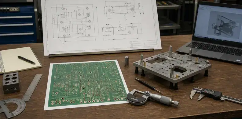
A connector can have generous individual hole clearance and still fail because the two rows are shifted or rotated relative to the housing. Start with the mating drawing and decide which contacts, shells, guide pins, or board edges constrain the assembly. Then establish a datum scheme that an inspector can recreate. For example, a primary board face may set seating, two locating holes may establish rotation and lateral position, and the connector pattern may be evaluated relative to those references. The fabrication drawing should make this relationship visible without forcing the shop to infer it from nominal coordinate values. That approach also prevents a routed outline from being used as the inspection origin when the enclosure actually locates from plated slots or guide holes.
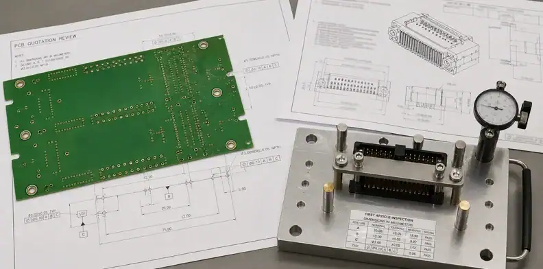
A press-fit example shows why the inspection method must be named. The finished-hole diameter can be within tolerance, but a small positional error across a dense field can prevent all pins from entering together. A CMM, optical system, or dedicated gauge will each establish datums differently. Before requesting a report, agree whether the evidence is a measured position table, a mating gauge result, or both. A quote should identify the pattern reference and any required first-article evidence. It should not treat a pass statement on a generic drill certificate as proof that a connector with a specified shell and guide-pin geometry will assemble.
When a mismatch is found, preserve the board and capture the setup before changing the drawing. Photograph the fixture or mating part, identify the board revision, and record the measured direction and magnitude of the offset. This allows the team to distinguish a design-datum conflict from drilling variation, routing shift, or a connector tolerance issue. The corrective action may be a revised datum scheme, altered mechanical clearance, or an updated hole pattern. Each is a product decision with different consequences, so the failure should not be closed by casually tightening every coordinate on the next drill file.
A useful pre-release review can be performed with one drawing, one mating reference, and one inspection question. On the drawing, identify the primary, secondary, and tertiary datums exactly where they exist on the assembled PCB. On the mating reference, identify which features must align at the same time: guide pins, shell walls, latch windows, shield posts, or enclosure bosses. The inspection question then becomes explicit: can the supplier demonstrate the critical pattern relative to those datums by a stated optical setup, CMM program, or functional gauge? This is much stronger than asking whether the hole pattern is accurate. Also distinguish a coordinate that is merely informative from a position that governs fit. When a tolerance stack becomes tight, model or calculate the available clearance before changing the hole location requirement. A blanket tightening of all NC drill coordinates may raise cost while leaving the functional datum conflict unresolved. The final package should retain any agreed first-article method and define what happens when the result falls outside the requested condition: hold for engineering, remeasure with the correct datum fixture, or revise the product definition. That keeps a mechanical fit decision from becoming a silent purchasing exception.
Do not confuse a good-looking drill map with a controlled locating system. Coordinate data is necessary for fabrication, yet it becomes an acceptance definition only when the drawing says what is referenced and what functional relationship is protected. This is particularly important when an enclosure holds the board by slots, rails, or molded posts while a connector pattern is laid out from a CAD origin. In that situation, a supplier can meet nominal coordinates and still produce a pattern shifted relative to the real assembly. Tie the report to the assembly datums, retain the first-article setup for an unfamiliar interface, and revise the product drawing when a new mating part changes the datum chain. That process turns a dispute about drilled holes into an evidence-based fit decision.
FAQ
Does the NC drill file define tolerance?
No. It defines nominal drill locations; the drawing should identify the functional location requirement.
Should every hole have a position tolerance?
No. Apply it to features whose relationship changes fit, alignment, or connector engagement.
Do plated holes move?
The manufacturing sequence can affect finished features, which is why functional requirements and evidence should be agreed before release.
What should a first article include?
It should include the actual datum method and the critical pattern or fit result, not only a generic dimensional statement.
Get a critical-hole pattern review
Provide the drill data, datum view, mating drawing, critical-hole schedule, and requested gauge or measurement method to QueenEMS. That lets the quotation address the functional pattern rather than only nominal drill coordinates.
Sources
Written by the QueenEMS Engineering Team
Upload your files today · Free DFM check before production · Ship worldwide
Get your PCB prototypes in as fast as 24 hours. We handle FR4, Rogers, and hybrid boards up to 40 layers in volume production, with advanced builds subject to engineering review — free prototypes for 2–4 layer FR-4 boards, no minimum order.
Just upload your Gerber + BOM — we source every part, assemble, and inspect (AOI + X‑Ray) so you don't have to chase suppliers. Boards ship in as fast as 24 hours.