
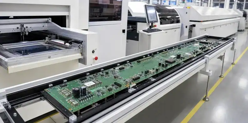
Quick Answer: Large format PCB assembly is feasible only when the board, carrier and populated product fit every required operation: solder paste printing, paste inspection, placement, conveyor transfer, reflow, AOI, through-hole work and test. Bare-board fabrication size does not prove SMT capability. Qualify the exact board outline, thickness, weight, edge support, component map and travel orientation against the complete assembly line before releasing the build.
Large format PCB assembly can fail at the handoff between two individually capable machines. A placement system may reach every coordinate, yet the stencil printer cannot support the board. The conveyor may accept the width, yet a tall connector collides with a downstream sensor. The reflow oven may have enough clearance, yet the board sags between rails.
The right sourcing question is therefore not “What is your largest SMT size?” It is “Which route will this exact assembly follow, and what supports, rails or exceptions does each step require?” That question produces a buildable answer and exposes the point that controls cost or feasibility.
Table of Contents
- Separate large format PCB assembly from bare-board limits
- Map the full assembly line
- Qualify solder paste printing
- Confirm placement travel and support
- Profile reflow across the entire board
- Plan inspection, THT and testing
- Run a controlled first article
- Quote the actual assembly route
Separate large format PCB assembly from bare-board limits
Fabrication and assembly use different equipment, tooling and handling rules, so their maximum dimensions must be approved separately. A board that can be imaged, drilled and routed is not automatically compatible with an SMT line.
The large format PCB manufacturing capability lists standard bare-board envelopes by layer count. Assembly review begins again with the finished outline and adds board thickness, total mass, component height, populated weight distribution, edge clearance and process sides.
Orientation can change the answer. A long narrow board may fit the conveyor when its short dimension spans the rails, but the travel length may exceed printer or placement indexing. Rotating the board may solve one operation and break another. Keep the proposed travel direction visible on the assembly drawing.
Tooling edges also matter. A bare board may use nearly the full material width, while the SMT process needs continuous rails for conveyor grip and support. If removable rails are required, define when they are removed and whether the finished product tolerates tabs or routed edges.
Use two lines in the sourcing record: “bare-board route confirmed” and “assembly route confirmed.” Do not allow one approval to stand in for the other.
Map the full assembly line
The governing assembly limit is the smallest usable window in the required sequence. Build a route map before comparing suppliers.
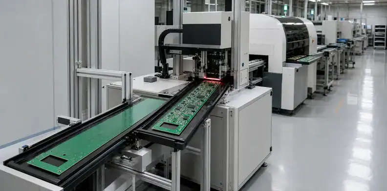
A typical SMT route may include board loading, solder paste printing, solder paste inspection (SPI), placement, pre-reflow inspection, reflow, automated optical inspection (AOI), X-ray where required, through-hole insertion, selective or manual soldering, cleaning, programming and functional test. Not every product uses every step, but every required step needs a size and support decision.
For each operation, record:
| Operation | Qualification question |
|---|---|
| Loader/conveyor | Can the board or carrier enter, transfer and stop repeatably? |
| Printer | Does the stencil, table and underside support cover the full print area? |
| SPI | Can the system image the full board and maintain board registration? |
| Placement | Can the machine access every coordinate with the required feeders installed? |
| Reflow | Are width, height, support and thermal profiling compatible? |
| AOI/X-ray | Is the full inspection area accessible at useful resolution? |
| THT/selective solder | Can the board be held without shadowing or flex? |
| Test | Does the fixture or probe field accept the outline and support load? |
The route should also show manual transfers. A process can fit mechanically but remain unsafe if operators must lift a high-value board by unsupported corners. Specify trays or carriers early enough to include them in the quote.
Route rule: Approve the job only after every automatic and manual transfer has an accepted board-or-carrier condition.
Qualify solder paste printing
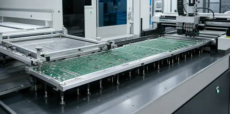
Consistent stencil contact requires a flat, supported board over the complete paste area. A large bed alone does not guarantee an acceptable print.
The supplier should confirm maximum stencil frame, printable field, board support method, fiducial access and squeegee travel. For double-sided assembly, bottom-side components or irregular hardware can prevent ordinary underside support. A dedicated tooling plate or carrier may be needed.
Read the type of dimension before comparing equipment. FRITSCH specifies a 1,170 × 630 mm printing area for printALL210XL, separately from its 1,420 × 750 × 43 mm maximum stencil size. Stencil-frame fit alone does not confirm coverage of the printed field. Check the active printing area against every paste location.
For placement, Mycronic lists boards up to 1,000 × 609 mm with the T1000 conveyor on MYPro A41, together with thickness and weight limits. These public examples describe different operations and configurations; they do not establish a compatible production line or QueenEMS equipment ownership. Ask the assembler to identify the actual configured route and carrier envelope.
Warpage matters directly. A board can meet bare-board acceptance yet still create local gasketing gaps under the stencil. Those gaps change paste deposit volume, especially around fine-pitch pads and bottom-terminated components. Connect the assembly review to the PCB bow and twist acceptance method and define whether incoming flatness is checked before printing.
Do not assume two separate stencil prints are acceptable on a board longer than the printer field. Overlapping prints create registration, paste disturbance and support questions. Such a route requires supplier-specific process development and should not be presented as a standard workaround.
The assembly package should identify critical paste regions, local fiducials, global fiducials, tooling edges and any component keepouts needed by supports. Siemens notes that stencil aperture design and fiducial strategy are fundamental parts of assembly preparation; large boards make their relationship to the machine field more visible.
Confirm placement travel and support
Placement qualification must cover coordinate reach, board indexing, fiducials, feeder access, z-height and support under the populated mass. A nominal board-size specification answers only part of this list.
Ask whether the board remains stationary, indexes through the machine or uses a carrier. If it indexes, the program needs a reliable coordinate and fiducial strategy for each region. The board must not lose support or shift between stages. The supplier should explain how global and local alignment are maintained without exposing paste to unnecessary handling.
Component map matters. Large or heavy parts may require special nozzles, feeder positions or manual insertion. Tall components on one side can interfere with second-side support. Parts close to the edge may conflict with conveyor grip, clamps or carrier walls.
Include centroid data, package heights and the heaviest components during quotation. The PCB assembly quote file requirements help control BOM and placement data; the large-format review adds physical support and machine travel.
Placement accuracy must be judged at the pad, not by the size of the machine. A long board with small components still needs stable local alignment. If connectors at opposite ends must mate to one enclosure, link placement and fabrication datums to the mechanical drawing.
Placement check: Machine travel is insufficient evidence unless support, indexing and local alignment remain valid at the farthest component.
Profile reflow across the entire board
A large assembly needs a measured thermal profile that brings cold and hot regions through the soldering window without exceeding component or laminate limits. Oven width is only the first feasibility check.
Thermal mass can vary across power planes, shields, connectors, BGAs and sparse logic zones. Nexperia AN10365 describes the central profiling problem: cold spots heat more slowly while small deposits and components may become hot earlier. Oven settings must bring both into an acceptable process window.
Select thermocouple locations from the actual risk map. Include a heavy copper or connector zone, a sparse region, a thermally sensitive component and any area near the leading or trailing edge that may respond differently. Record attachment method and component limits so the profile can be repeated.
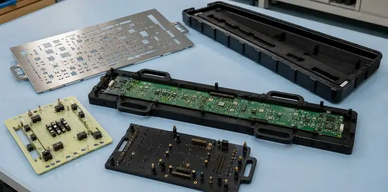
Mechanical support continues through reflow. The board is less stiff at elevated temperature, and heavy components can increase local sag. Conveyor center support or a carrier may be required. The carrier itself changes thermal mass, so it belongs in the profiling configuration rather than being added after the recipe is established.
Cooling deserves attention as well. Uneven support or rapid temperature differences can lock residual stress into the assembly. The objective is not a generic oven recipe; it is evidence that the actual board and tooling completed the qualified profile.
Plan inspection, THT and testing
Post-reflow operations need their own fields, fixtures and support plan. A successful soldering pass does not make a board inspectable or testable.
AOI must cover the complete board at a useful resolution and angle. Tall components can create shadowed regions. A large board may require indexing, which needs a stable reference strategy. X-ray inspection for BGAs or hidden joints should be planned by risk rather than promised as a generic full-board scan.
Through-hole connectors are common on industrial large boards. Confirm whether they are manually soldered, wave soldered or processed by selective soldering. The board and carrier must fit the equipment, and heavy connectors need mechanical support before their joints carry load.
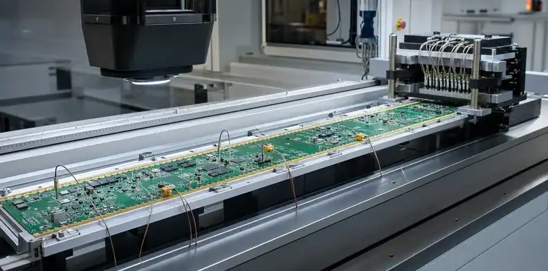
Test can become a mechanical problem. A bed-of-nails fixture applies force through many probes; inadequate underside support can flex the board and create false contacts or strain. Flying probe avoids a dedicated fixture but still has a physical field and access requirement. Define programming, electrical and functional test scope in the RFQ using the PCB electrical test requirement process.
The quality plan should name what evidence will be delivered: SPI/AOI result where applicable, X-ray for agreed parts, first-article measurements, test record and any flatness or fit check. Link those records to the actual revision and lot.
Evidence point: Release the first article only when thermal, inspection and test records cover the actual supported route.
Run a controlled first article
The first article should prove the route, not merely produce one electrically working assembly. Observe each operation that had a size, support or thermal assumption.
Before printing, verify incoming board condition, carrier fit, tooling edges and fiducials. Inspect the first paste print at critical regions before placement continues. During placement, confirm indexing, component access and board support. Capture the final thermal profile with the intended carrier and conveyor configuration.
After reflow, inspect critical joints and measure any flatness or connector-fit condition that drove the review. Continue through THT, programming and functional test using production-intent fixtures. A board that works only after an operator improvises additional hand support is not yet a released route.
Use a hold point before the remaining lot. The approval record should state what passed, what changed and whether the change affects tooling, program, profile or board data. The PCB first-article inspection approach provides a broader receiving context; this assembly release should concentrate on the size-dependent route.
A contextual manufacturing review is useful before tooling is ordered. Send the board outline, thickness, weight estimate, BOM, centroid, assembly drawing and process sides. The return should identify the limiting equipment, required carrier or rails, and first-article evidence.
Quote the actual assembly route
A comparable quotation must show the equipment route, tooling and exceptions that make the large assembly feasible. Otherwise a low quote may be based on manual work or omitted inspection that appears only after order placement.
Request separate lines or assumptions for stencil, carrier, special support, programming, inspection, X-ray, THT labor, test fixture and packaging. Clarify tooling ownership and repeat-order storage. If a process remains provisional, keep it visible rather than treating it as included.
Revision control is critical because a small layout change can move a fiducial, add a tall part near the rail or shift thermal mass. Recheck the route when outline, thickness, component side, heavy parts, connector location or test access changes.
In the sourcing record, large format PCB assembly describes physical board dimensions; large-volume PCB assembly describes order quantity or throughput. State both dimensions and quantities so that the supplier reviews the relevant constraints.
For a QueenEMS quotation, send Gerber/ODB++, BOM with manufacturer part numbers, centroid data, assembly drawings, board dimensions and thickness, largest/heaviest components, quantity breaks, test requirements and delivery destination. The review can return a route-specific quotation and identify which assumptions need engineering approval.
Ask the supplier to return a process-route table with a disposition for every operation. Automatic, indexed automatic, carrier-assisted, manual and not available are more useful than a single yes/no answer. The table should identify the usable field, travel direction, edge requirement and any keep-out zone that affects the layout. Where two machines perform the same operation, record which one is quoted so that a repeat order does not silently move to an unqualified route.
The quotation also needs a handoff rule between automatic and manual work. Manual placement or soldering can be valid for prototypes, but it changes labor, consistency, inspection and capacity. Define which reference designators are manual, how polarity and value are verified, and what inspection record closes the step. For production, ask whether the manual content has a practical throughput ceiling or requires a fixture.
Packaging is part of the route for an oversized PCBA. Specify whether the finished assembly ships in an ESD bag, tray, partitioned carton or reusable rack. Identify fragile connectors, unsupported corners and components that cannot carry stacking load. If the populated board is heavy, agree on lift points and maximum stack height. A technically good assembly can still arrive damaged when the packaging plan treats it like a standard board.
Separate one-time qualification from recurring unit work. Stencil, carrier, support tooling, test fixture, thermal profiling and first-article inspection may be non-recurring. Placement, inspection, manual operations, functional test and protective packing recur. This split makes supplier comparisons clearer and shows what must be requalified after a revision. Record the approved route with the PCB quality documents required before shipment so the evidence package is defined before production.
| Quote category | Typical content | Revision trigger |
|---|---|---|
| One-time tooling | Stencil, carrier, support and test fixture | Outline, rail, support or test-point change |
| Qualification | Thermal profile and first-article evidence | Stack, mass distribution or process-side change |
| Recurring automatic work | Placement, reflow and programmed inspection | Component or program revision |
| Recurring manual work | Hand insertion, soldering and verification | Reference-designator or work-instruction change |
| Logistics | ESD protection, tray and reinforced shipping | Weight, connector or packing revision |
For an equipment-route quotation, send QueenEMS the board data and complete PCBA package, including board weight, component heights, process sides and test scope. The returned disposition can identify automatic, indexed, carrier-assisted or manual operations and separate one-time tooling from recurring assembly work.
Bottom line: The commercial quote is buildable only when every route exception and its tooling cost are visible.
FAQ
Can a fabricable 1000 mm PCB be assembled automatically?
Not automatically. The printer, placement system, conveyor, oven, inspection and test route must each accept the board or its carrier.
Can placement be completed in two passes?
Possibly on qualified equipment, but indexing, fiducials, support and paste handling must be validated. It should not be assumed during design.
Does a large board always need a carrier?
No. The need depends on thickness, span, edge support, populated mass and thermal behavior. The assembler should decide from the actual board.
What information is needed before quoting assembly?
Provide the bare-board data, BOM, centroid file, assembly drawings, dimensions, thickness, component heights/weights, process sides, quantities and test scope.
Is AOI available for every oversized board?
No universal answer applies. The system field, indexing method, component shadows and required resolution must be reviewed for the specific assembly.
Sources
Written by the QueenEMS Engineering Team
Upload your files today · Free DFM check before production · Ship worldwide
Get your PCB prototypes in as fast as 24 hours. We handle FR4, Rogers, and hybrid boards up to 40 layers in volume production, with advanced builds subject to engineering review — free prototypes for 2–4 layer FR-4 boards, no minimum order.
Just upload your Gerber + BOM — we source every part, assemble, and inspect (AOI + X‑Ray) so you don't have to chase suppliers. Boards ship in as fast as 24 hours.