
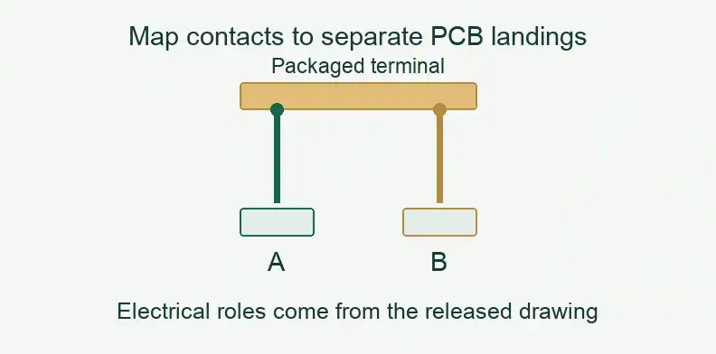
Quick Answer: When a DPS detects an open by comparing FORCE and SENSE, the point where those paths first join limits what that comparison can reveal. Joining them on the PCB can leave a packaged-device contact outside the comparison. Before ordering, record both contact positions, their PCB landings and their first join from the released contactor and circuit drawings.
Featured image: Illustrative geometry only. A/B are drawing identifiers, not assigned force and sense roles.
This guide concerns the order record for a customer-designed Kelvin contactor interface. It uses the AD5560 as a part-specific example of configuration-dependent evidence; it does not establish a validated combination of that DPS and any named contactor.
Why does the force/sense join point matter on a Kelvin load board?
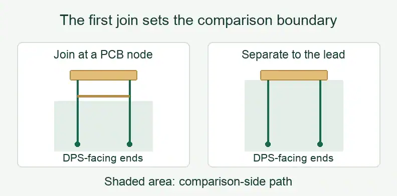
For an open detector that compares force with sense, the first electrical join defines the comparison boundary. Independent paths reaching a packaged lead provide a different boundary from paths joined at a PCB node. The order record should identify the intended join, rather than relying on the word Kelvin alone.
The AD5560 description explains that its open-sense detector compares the FORCE and SENSE lines. From that comparison logic, an open between their first join and the device lead may leave both lines connected to the same board node. This is an inference about the comparison boundary, not a universal statement about every DPS detector.
Name the first join in the released circuit. If it is intended to occur through two contacts at the lead, identify those contacts and both board landings. If the paths join earlier, record that node and leave later contact coverage to the test owner’s applicable evidence.
The existing large-board power-distribution guide covers general remote sense, voltage-drop budgeting and transient considerations. Here the task is to preserve the contact-to-landing boundary.
What do current Kelvin contactor sheets actually show?
Currently offered vendor sheets show independent force and sense paths and paired contacts with separate PCB-side landings. They support the existence of that contact arrangement, but cannot assign roles to the landings on your board. Use the released contactor drawing and circuit data for those assignments and the intended join.
Cohu’s cPython product sheet describes electrically isolated, mechanically independent force and sense paths. It covers packaged devices and distinguishes the DUT-side and board-side tips. It also directs interface-hardware design to the contactor drawing.
The currently linked Smiths Interconnect Kelvin probe catalogue shows paired contacts at package pads and separate board-side contacts. Its illustrated pair does not label the electrical roles. Neither source establishes that every terminal in an ordered contactor uses that arrangement.
These are dated sheets still offered by their vendors: Cohu’s sheet carries a 2020 revision identifier and 2021 copyright, and Smiths’ catalogue is Version 1.0 from 2021. No pitch, spacing, resistance or current figure from either sheet is adopted as an order requirement.
How do you tie each contact to the right PCB landing?
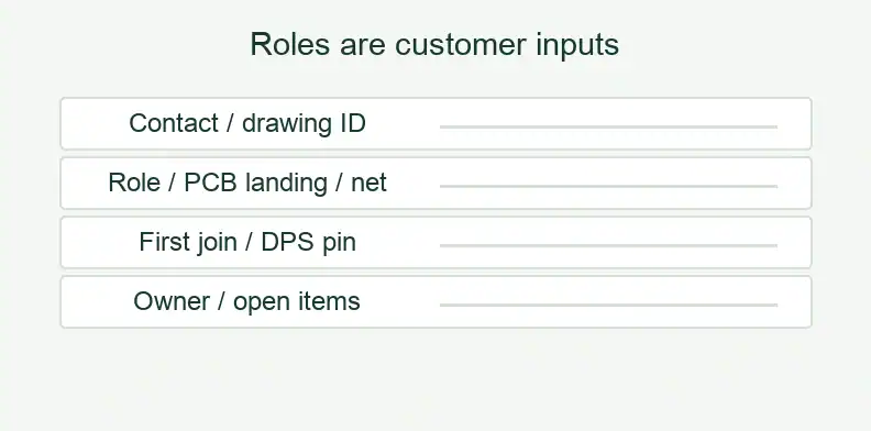
For each intended Kelvin terminal, map the two contact positions from the released drawing to their electrical roles, PCB landings and nets. Then identify the first join and the relevant DPS pins. Two contacts touching one terminal do not alone establish separate force and sense roles; the released connection data must establish them.
A pair can also carry the same signal in parallel for redundancy, as Loranger’s 2014 note on Kelvin contacts distinguishes. Do not infer a Kelvin role from the count of probes or from the shape of an unlabelled footprint. Preserve any unassigned role as an open item for the design owner.
The following Kelvin contact-to-landing boundary record is an editor recommendation. It gives the customer a place to resolve the mapping before the fabricator builds the released data.
| Record field | Customer-supplied entry |
|---|---|
| DUT terminal | Package pin or ball and applicable device variant. |
| Contactor identity | Drawing ID, revision and contact positions A/B as defined there. |
| Role per contact | Force, sense, parallel redundant or unassigned; cite the circuit. |
| PCB landing | Landing reference and net for each contact. |
| First join | At the lead through the contacts, at a named PCB node, or elsewhere. |
| DPS connection | Channel and FORCE, SENSE or DUTGND pin reference. |
| Intervening interfaces | Connectors or relays inside the path; transition requirements handled separately. |
| Disposition | Responsible owner and unresolved mapping items. |
Keep drawing contact IDs and board landing IDs separate even when they look similar. A supplier question can then cite the exact unresolved mapping instead of asking whether the board is generally “Kelvin compatible.”
What can a DPS open-sense or DUTGND alarm prove?
An alarm reflects its configured detector and connected boundary; it does not directly prove that both contacts touched a packaged lead. Identify the DPS part, enabled alarms, holding-switch state and latch settings with the result. A shared alarm output also needs interpretation against the conditions that can assert it.
The Analog Devices AD5560 data sheet, Rev. F, describes open-sense detection and a switchable force-to-sense holding resistor intended for the no-DUT condition. It states that leaving the resistor connected during measurement defeats open-circuit identification. This describes the AD5560; another DPS may behave differently.
The same document describes a DUTGND pull-up that can be disabled and an alarm that can be latched or unlatched. KELALM is shared by sense opens, DUTGND opens and a guard short. A report should therefore identify the applicable detector configuration and interpretation rather than translate “no KELALM” into “both contacts made contact.”
The linked copy is ADI’s Rev. F (revision history November 2022), hosted by a distributor; check Analog Devices for any later revision. Detector thresholds, delays and operating steps belong to the applicable data sheet and the test owner’s method.
Which DPS compensation assumptions depend on the contact path?
The compensation mode, fitted external components and entered load assumptions describe a particular circuit and contact path. Record them against the contact mapping boundary. If the ordered configuration differs from the one under which the evidence was produced, the test owner must decide applicability; the board order cannot supply a stability or settling guarantee.
AD5560 Rev. F describes safe, automatic and manual compensation modes. The load range covered by its safe-mode stability statement depends on which external compensation capacitors are fitted. Automatic compensation uses entered load capacitance and ESR with a path-resistance assumption; the document also discusses parallel load capacitors. These dependencies belong with the configuration evidence, without importing their numerical values.
The DPS configuration evidence card below is a second editor recommendation. It records which assumptions the owner’s evidence covers; it provides no tuning method or load-step test.
| Configuration field | Evidence reference to retain |
|---|---|
| DPS identity | Part, data sheet revision and channel. |
| Compensation | Mode and fitted external components by BOM or variant reference. |
| Load inputs | Capacitance and ESR used, with their source. |
| Path assumption | Applicable path and whether it includes the contactor. |
| Alarm configuration | Enables, latch settings and holding-switch state during measurement. |
| Boundary | Contact-to-landing record reference and first join. |
| Result ownership | Owner, evidence configuration, covered boundary and open items. |
What can a board supplier check, and what stays with the test owner?
The supplier can check manufactured copper and nets against released data, including the specified separation up to the contact landings. Assembly and its checks are agreed per order. The customer retains contactor design, DPS configuration, calibration and system correlation, with evidence identifying the actual device-contact boundary and configuration evaluated.
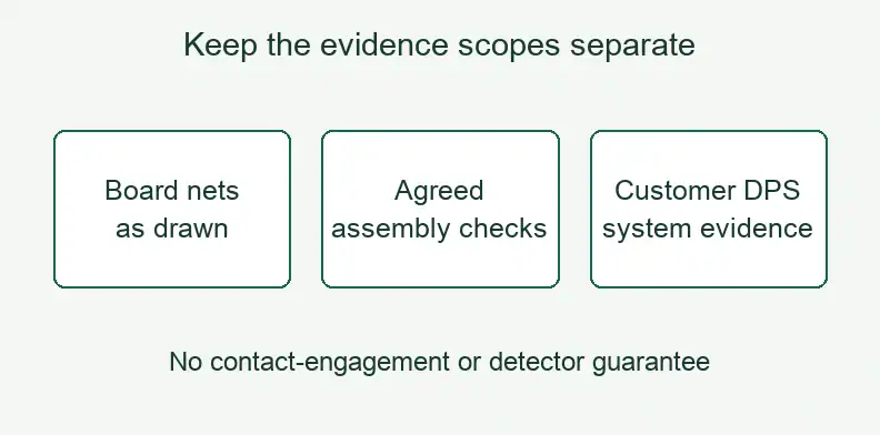
The ATE PCB manufacturing page defines the manufacturing inquiry. State the required fabrication or assembly checks in the quotation. A net check can address the board connections within its scope; it cannot establish contact engagement at the packaged device or validate the DPS detector.
When the released files leave a landing role or join unresolved, return the question to the design owner. Keep the manufacturing reply attached to the supplied revision and agreed check instead of treating it as system-level evidence.
What else should buyers ask about Kelvin load boards? (FAQ)
Confirm the contact arrangement, released role mapping and detector configuration before interpreting a Kelvin label or alarm report. These questions concern different parts of the evidence chain. Missing drawing information belongs with the design owner, while the supplier quotation should identify which construction and assembly checks are actually included.
Is every contact on a Kelvin contactor a force/sense pair?
No. Identify which terminals use paired contacts and their assigned roles from the released drawing and circuit. A product-family label cannot supply that mapping.
Can I tell force from sense on a vendor footprint drawing?
Only if the applicable drawing explicitly assigns those roles. An unlabelled pair establishes geometry, not the electrical role of each board landing.
If the DPS shows no Kelvin alarm, are both contacts touching the lead?
That conclusion needs the test owner’s evidence. The first join, holding-switch state, detector enables and shared alarm functions can limit what the reported alarm establishes.
Send your released files for a quote and free DFM review.
Send Gerber, drill data, stackup and drawings for a PCB quote. Include the contact-to-landing map, net references and force/sense roles.
For assembly, add the BOM and drawings for the specified contacts and fitted parts. Agree board checks separately from system validation.