
Quick Answer: A relay-matrix netlist shows what can connect, not which combinations are allowed or what happens while contacts change state. Before ordering, freeze the allowed and forbidden states, the power-off and reset state, and the conditions for each transition. Then compare the actual switched voltage, current and load against the relay’s switching rating, not its carry rating.
Featured image: Generic AI-generated illustration; not a QueenEMS board or an approved matrix state.
Standex Detect describes relay matrices and distributed routing on semiconductor load boards and probe cards. These connections let instruments reach different DUT pins or test modes. For a customer-designed ATE relay-matrix PCB, the order needs the approved connection rules alongside the fabrication files.
Why isn’t a relay-matrix netlist a state definition?
A netlist describes electrical interconnections, while a matrix state identifies which relay contacts connect particular endpoints at that moment. The same hardware may permit several simultaneous connections. Purchasing therefore needs the customer’s approved state definitions and their relationship to the implemented circuit, beyond the fact that individual paths exist.
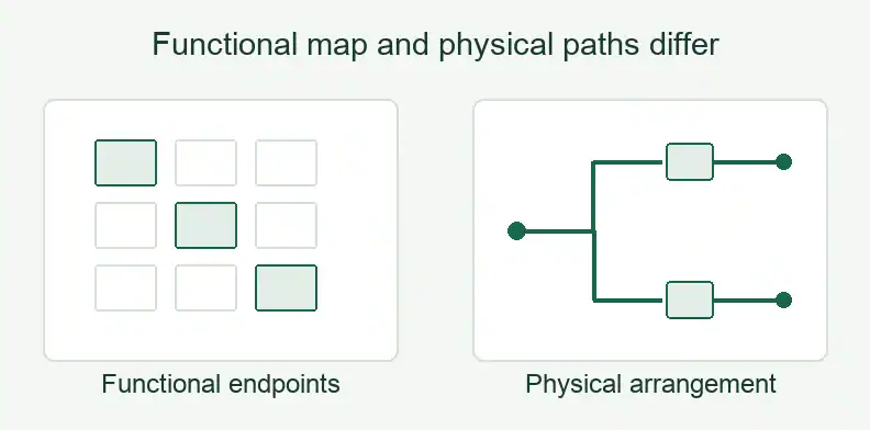
Pickering’s white paper, Using Switch Matrices in Complex Test and Verification Installations, distinguishes functional crosspoint drawings from physical crosspoint or tree implementations. A functional drawing can hide the relays and intermediate connections used to create a route. Its appearance cannot establish the actual contact combination.
Give each source or instrument endpoint and each DUT endpoint an unambiguous name. Tie the route to the released schematic and relay contact identifiers. If a design uses paired routes, identify their required association without inferring measurement accuracy from that association.
An approved connection state answers which endpoints may be joined together. A transition definition adds what may occur while changing those connections. Both belong to the customer’s design and test requirements before an assembly check can be meaningfully specified.
Which combinations must be explicitly forbidden?
List connections the customer prohibits, including combinations that individually valid relay closures could create together. Matrix flexibility can connect several endpoints at once. MARVIN describes the consequences of software errors or a stuck relay, so an allowed-route list alone leaves the treatment of unintended simultaneous connections unresolved for the design owner.
MARVIN’s matrix discussion warns about connecting low-impedance sources together. Pickering’s white paper also describes excluding unwanted routes, such as power-to-ground connections. These are reasons to identify prohibited endpoint combinations; they do not supply the complete exclusion rules for your board.
Record the relevant state or combination, the affected endpoints, and the customer owner responsible for its disposition. Ask the design owner to identify where the rule is implemented and what supporting evidence is required. The PCB supplier should receive the approved requirement rather than invent an interlock or protection circuit.
Treat an unanswered combination as an open design item. A relay closure that is valid in one test mode may be prohibited when another source is connected. Keep mode-dependent permissions explicit instead of assuming every route shown on the drawing may be used concurrently.
What state is the matrix in at power-off, at reset and between states?
Specify the actual contact connections at power-off and reset, then define each permitted transition separately. Contact form and the selected relay’s latching or non-latching behavior belong in that record. A control label such as “off” does not identify every connected endpoint, and a stable-state drawing leaves the intervening contact sequence undefined.
Pickering’s switch-form introduction identifies Form A as normally open and Form B as normally closed with no coil power. Form C is changeover. Those descriptions help interpret a schematic, but the selected component and control design must establish the board’s actual power-off and reset states.
MARVIN distinguishes make-before-break, where the new connection is made before the previous one breaks, from break-before-make, where the previous connection breaks first. Record the customer’s rule for each transition; neither name, by itself, approves the load conditions during that transition.
The following Allowed-state and Transition Contract is an editorial procurement suggestion, not a standard or validated control program. Complete it for each approved transition and retain unresolved entries.
| Contract field | Customer-approved information |
|---|---|
| Design revision | Released schematic and board revision. |
| Source/instrument endpoint | Named source or instrument connection. |
| DUT endpoint | Destination and applicable test mode. |
| Relay/coil/contact ID | Identifiers linking the route to the circuit. |
| Allowed and forbidden combinations | Approved simultaneous connections and exclusions. |
| Power-off and reset state | Actual connections; latching/non-latching identification. |
| From-state → to-state | Identified starting and destination states. |
| Transition rule | MBB, BBM or another customer-defined rule. |
| Source enabled during switching? | Yes, no or unknown, with the applicable condition. |
| Measurement-permitted condition | Customer criterion for accepting a reading. |
| Owner | Person approving the connection and transition requirements. |
| Open items | Unresolved condition and required disposition. |
Why isn’t carry current a switching rating?
Carry current describes current through contacts that are already closed. Switching exposes the contacts to the conditions present as they make or break a connection. The switched voltage, current, power and load characteristics need their own review against the selected relay’s applicable ratings; the carry value cannot supply that review.
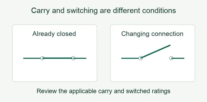
MARVIN’s ATE switching guide separates maximum carry current from switched current and discusses switching power. Retain the OEM’s stated conditions beside each rating instead of treating the largest current on a datasheet as permission for every operation.
Hot switching means contacts open or close with a signal present. Cold switching describes the signal-free switching condition. This terminology concerns the electrical condition at the contacts, rather than whether the test board is physically hot.
Pickering’s Hot Switching Relays guidance explains that capacitance in cabling or the load, including residual charge, can change the closing event. In its power-supply example, initial charge transfer between supply and load capacitors is not constrained by the supply’s current-limit circuit. A steady current setting therefore leaves that transient condition unanswered.
Use this Carry-versus-switch Requirement Card as a second editorial suggestion. It records questions for the component OEM and customer, with no universal delay, discharge criterion or derating value implied.
| Requirement field | Information to return |
|---|---|
| Carry current | Required current while the contacts remain closed. |
| Switched voltage/current/power | Conditions at making and breaking the route. |
| Load and stored charge | Load type, residual-charge and capacitance conditions. |
| OEM rating and test condition | Exact component document, revision and applicable rating. |
| Settling/bounce and temperature | Conditions applicable to the intended transition and reading. |
| Configuration | Assembly, firmware and test-program revisions. |
| Evidence source | Bare-board netlist, assembled check or customer live-switching validation. |
| Unknowns | Missing data, decision owner and disposition needed. |
When is a measurement valid after a transition?
The customer must define the condition that permits a measurement after the contacts change state. MARVIN distinguishes actuation and release times and includes contact settling or bounce in its discussion. A relay command, a nominal timing entry and an approved measurement condition therefore describe different parts of the switching and measurement sequence.
Put the measurement-permitted condition in the transition contract. Reference the selected relay’s applicable timing information and the customer’s test-program requirement, including the configuration under which the condition applies. Leave an unestablished condition open for the test owner.
This record does not prescribe a waiting period. It asks the test owner to identify the basis for permitting the reading and the evidence that supports it. Any requirement for additional measurement-system settling belongs in that owner’s approved method.
Keep contact behavior, source state and measurement permission associated with the same transition. Otherwise, a test log may name the destination route while leaving unclear whether its reading occurred under the approved conditions. Changing firmware or the test program requires reviewing the affected contract entries.
What can a board supplier prove, and what stays with the test owner?
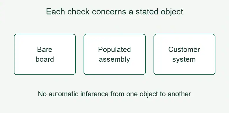
The supplier can return evidence for the fabricated interconnections and the populated checks agreed in the order. Those records have defined coverage. The customer retains the connection rules, relay-control firmware, test program and live-switching validation. A passing bare-board netlist check cannot establish how the assembled matrix behaves during an energized transition.
QueenEMS’s ATE PCB manufacturing service follows customer-released design data, with optional assembly confirmed during quotation. Define any requested assembled checks explicitly. Matrix design, control firmware and live-switching qualification are outside this manufacturing scope.
For each requirement card, identify whether the offered evidence comes from the bare board, an agreed assembled check or customer system validation. An assembly result supports the connections and conditions actually checked; record anything left for the customer’s test setup.
Use the existing ATE load-board acceptance and failed-path guide for staged release and investigation after a failure. The state and transition records here supply the approved requirements against which that later work can be planned, without replacing the acceptance or repair record.
What else should buyers ask about relay-matrix PCB orders?
Confirm the permitted connection combinations, transition conditions and evidence that the order will deliver. Ask who provides the control firmware and test program, which component ratings apply, and who approves power-off behavior. These decisions remain project-specific, even when the same relay or PCB revision is reused.
Can the PCB supplier write the relay control firmware?
No. Do not assume firmware accompanies a PCB quotation. QueenEMS’s scope covers fabrication from released customer data and optional agreed assembly. The customer or its design partner supplies the relay-control firmware, connection rules and test program, and owns validation of their behavior in the intended test system.
Does a cold-switch life rating cover hot switching?
No. Retain the signal and load conditions associated with the OEM life data. Hot-switching use needs applicable component evidence and customer review; a cold-switch life figure alone does not cover it or guarantee damage-free operation.
Do I need a BOM for a bare relay-matrix board quote?
No. Gerber, drill files, stack-up and fabrication drawing define the bare-board request. Include a BOM when requesting assembly, and identify the agreed checks and any customer requirements still open.
Is a Form C relay safe by default at power-off?
Form C identifies changeover contacts, not an approved safe state for your circuit. Check the selected relay and control design, then have the customer approve the actual power-off and reset connections and their permitted use.
Send your released files for a quote and free DFM review.
Send Gerber, drill files, stackup and drawings for a PCB quote. Include approved relay states and transitions, with open questions flagged.
For assembly, add the BOM, relay part numbers and fitted positions. Agree inspection scope against the approved switching and power-off requirements.