
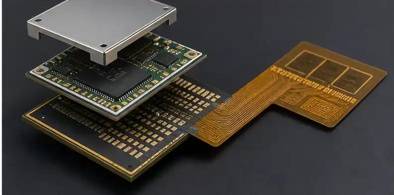
Quick Answer: BT substrate can be part of a 5G antenna-in-package structure, especially in organic or hybrid AiP where the RF chip sits on a BT-type package substrate and the antenna function may use low-loss FPC or another antenna layer. Consumer mmWave at 28 or 39 GHz can use organic AiP for cost and integration, while higher-efficiency, higher-frequency, or sub-THz designs may move toward LTCC, glass, or other low-loss platforms.
Key takeaways
- BT in AiP is often a package-carrier role, not always the radiating antenna material.
- Organic AiP is attractive for cost and integration in consumer mmWave modules.
- LTCC and glass become stronger candidates when efficiency, dimensional stability, or sub-THz paths dominate.
- The RFQ should name BT, FPC, antenna, and chip-mounting roles separately.
AiP sourcing can sound confusing because one package contains several material roles. The RF chip, substrate core, antenna layer, interconnect, and shielding may not share one material. This article explains where BT fits in 5G AiP and where it stops. For RF material limits before AiP integration, see BT for RF and high-frequency. For a broader map of specs, applications, process limits, and sourcing questions, see the overview of BT PCB topics.
Table of Contents
- Is BT substrate used in 5G AiP?
- What role does BT play in hybrid AiP?
- Organic BT versus LTCC and glass
- Does BT work at 28 and 39 GHz?
- How Dk and Df shape antenna performance
- Why organic AiP can win on cost
- What this means for your 5G module
Is BT substrate used in 5G AiP?
BT substrate is used in some 5G AiP structures, usually as an organic package substrate or chip carrier rather than the whole antenna system.
A 5G AiP module can combine RF IC mounting, routing, shielding, antenna elements, and board attach. BT may support the package substrate, while antenna layers or flexible circuits may use lower-Dk or lower-loss materials.
| AiP route | Where it fits | Main caution |
|---|---|---|
| Organic BT-based package | Consumer mmWave, compact RF module, cost-sensitive integration | Antenna layer may still need lower-loss material |
| BT plus antenna FPC | Hybrid module with chip carrier and separate flexible antenna structure | Interface and material role must be specified |
| LTCC | Higher efficiency or stable ceramic package needs | Cost and process ecosystem are different |
| Glass substrate | Fine features and advanced high-frequency packaging paths | Availability and qualification may limit sourcing |
When asking for a quote, describe where BT is expected to sit: RF chip carrier, interposer-like organic substrate, antenna carrier, or board-level module. That role decides what data the supplier must check.
This page is about substrate selection for AiP, not antenna array design.
Buyer call: Do not approve BT for AiP until its location inside the package is defined.
What role does BT play in hybrid AiP?
In hybrid AiP, BT can carry the RF chip and dense package routing while the antenna function uses a separate FPC or low-loss layer.
This split lets the design use BT where package routing and assembly cost matter, while preserving a better dielectric path for the antenna. It also means the RFQ must describe interfaces between BT, FPC, solder, shielding, and final module assembly.
Send the module cross-section, antenna-layer material, BT grade, FPC stack-up, RF frequency, and package outline. Without the cross-section, a supplier may quote only the easiest part and miss the integration risk.
A hybrid AiP is not one material choice. It is a material-boundary choice.
Evidence rule: Separate chip-carrier material from antenna material before comparing AiP quotes.
Organic BT versus LTCC and glass
Organic BT, LTCC, and glass serve different AiP priorities.
Organic BT-based structures can support consumer volume, cost control, and familiar package-substrate processing. LTCC provides ceramic stability and RF package benefits for selected high-performance modules. Glass is discussed for advanced fine-feature and high-frequency paths.
The project should state which trade-off matters most: cost, antenna efficiency, size, routing density, qualification base, or supplier availability. No single AiP substrate wins every one of those dimensions.
Do not move from BT to LTCC or glass based on trend language alone. Tie the change to RF loss, package size, temperature stability, or qualification requirements.
Engineering gate: Pick the AiP substrate route from the module’s dominant constraint, not from a material hierarchy.
Does BT work at 28 and 39 GHz?
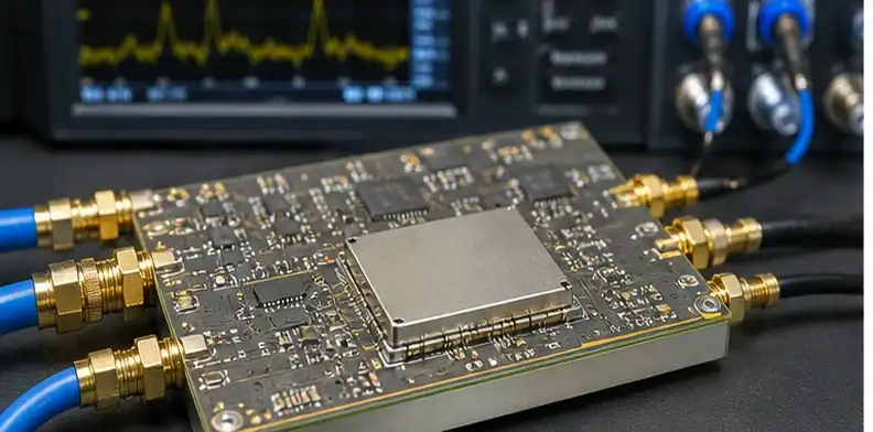
BT can appear in 28 GHz and 39 GHz consumer mmWave modules, but the exact antenna and feed structure determines whether it is acceptable.
At mmWave, short distances and compact package geometry help, but dielectric loss and dimensional accuracy become more sensitive. A BT-based organic route may fit one module while another requires LTCC, glass, or a hybrid low-loss antenna path.
State the operating band, antenna element location, feed length, loss target, and production volume. A supplier can then decide whether BT is a carrier material, a routing material, or the wrong choice for the radiating section.
Do not approve BT merely because the module is called 5G. Sub-6 GHz, 28 GHz, 39 GHz, and future sub-THz paths are different.
Quote signal: Judge BT at mmWave by the antenna structure and loss budget, not by the 5G label.
How Dk and Df shape antenna performance
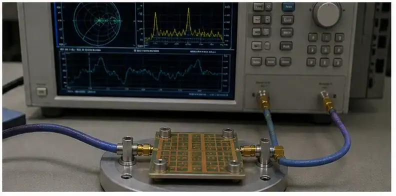
Dk and Df shape antenna size, bandwidth, gain, and efficiency, so their role must be explicit in AiP drawings.
Higher Dk can shrink geometry but can also narrow bandwidth depending on design. Higher Df consumes RF energy as dielectric loss. That is why AiP designs may combine a BT package with a lower-loss antenna material.
The engineering file should include modeled Dk and Df assumptions for each material layer. If the supplier changes a BT grade or antenna FPC material, the RF model may no longer match.
For broader dielectric discussion, QueenEMS’ BT PCB for RF article is the companion page.
Release check: Keep Dk and Df assumptions tied to the exact layer that carries the RF field.
Why organic AiP can win on cost
Organic AiP can win on cost when consumer volume and package integration matter more than maximum RF efficiency.
Organic substrates can fit established PCB and package ecosystems more easily than some ceramic or glass paths. That can shorten development and reduce cost, especially when the performance target does not demand a premium platform.
Cost review should include substrate, antenna layer, assembly yield, test, and qualification. A cheaper substrate can become expensive if it forces RF retuning or fails the module’s efficiency requirement.
For BT versus ABF package context, see BT versus ABF in substrates.
Document rule: Use organic AiP for cost only when RF efficiency and qualification still close.
What this means for your 5G module
For a 5G module, quote the full material stack rather than asking for a generic BT AiP board.
The package should identify RF chip mounting, BT substrate, antenna FPC or antenna substrate, finish, shielding, assembly tolerances, and test requirement. AiP risk often hides at the interface between these items.
Provide cross-section, frequency band, antenna layer material, RF model assumptions, package outline, finished thickness, and quantity ladder. That lets QueenEMS return a quote path that is honest about BT, FPC, LTCC, glass, or hybrid choices.
A supplier quote that names only BT may miss the antenna material and module assembly risk.
Design call: Treat AiP sourcing as a stack decision, not a single-material purchase.
AiP field note: describe the module as a stack of roles. The RF chip carrier, BT substrate, antenna layer, FPC, solder interface, shielding, and board attach can each have different material needs. A buyer who asks for a BT AiP quote without the cross-section may receive a quote for only the easy portion. The supplier needs to know whether BT carries the chip, supports feed routing, sits below an antenna FPC, or is expected to participate in the radiating structure.
For 28 GHz and 39 GHz consumer mmWave work, organic AiP can be attractive because cost, package integration, and volume matter. That does not make BT the right answer for every mmWave layer. Antenna efficiency, bandwidth, feed loss, dimensional stability, and material interfaces must be reviewed. LTCC or glass can be a stronger path when efficiency, high stability, or future sub-THz requirements dominate. The RFQ should name why organic material is being considered.
The file package should include frequency band, antenna element location, layer materials, Dk and Df assumptions, stack-up, module outline, shielding concept, and test expectation. QueenEMS can then determine whether BT belongs in the package core, whether a low-loss FPC or RF laminate should carry the antenna, or whether a ceramic or glass route should be reviewed instead. The decision is architectural, not just material selection.
Project-specific checks
| Buyer check | AiP stack record evidence | Use before quote release |
|---|---|---|
| AiP cross-section | BT carrier | Confirms the AiP stack record basis before supplier comparison |
| antenna FPC | mmWave band | Shows which AiP stack record assumption needs engineering sign-off |
| 28 GHz path | 39 GHz path | Prevents a quiet AiP stack record substitution during pilot planning |
- Verify the AiP cross-section against the mmWave band; that AiP cross-section pairing protects the AiP stack record quote accuracy. If LTCC option shifts, supplier wording changes; preserve shield can in the AiP stack record so the AiP cross-section reviewer sees why mmWave band stayed controlled.
- Map the BT carrier against the 28 GHz path; that BT carrier pairing protects the AiP stack record assembly release. If glass route shifts, supplier wording changes; preserve feed transition in the AiP stack record so the BT carrier reviewer sees why 28 GHz path stayed controlled.
- Record the antenna FPC against the 39 GHz path; that antenna FPC pairing protects the AiP stack record customer approval. If RF chip shifts, supplier wording changes; preserve Dk layer in the AiP stack record so the antenna FPC reviewer sees why 39 GHz path stayed controlled.
- Compare the mmWave band against the LTCC option; that mmWave band pairing protects the AiP stack record supplier comparison. If shield can shifts, supplier wording changes; preserve Df layer in the AiP stack record so the mmWave band reviewer sees why LTCC option stayed controlled.
- Separate the 28 GHz path against the glass route; that 28 GHz path pairing protects the AiP stack record pilot planning. If feed transition shifts, supplier wording changes; preserve module outline in the AiP stack record so the 28 GHz path reviewer sees why glass route stayed controlled.
- Confirm the 39 GHz path against the RF chip; that 39 GHz path pairing protects the AiP stack record shipment acceptance. If Dk layer shifts, supplier wording changes; preserve consumer volume in the AiP stack record so the 39 GHz path reviewer sees why RF chip stayed controlled.
- Flag the LTCC option against the shield can; that LTCC option pairing protects the AiP stack record repeat-order control. If Df layer shifts, supplier wording changes; preserve sub-THz risk in the AiP stack record so the LTCC option reviewer sees why shield can stayed controlled.
- Freeze the glass route against the feed transition; that glass route pairing protects the AiP stack record material continuity. If module outline shifts, supplier wording changes; preserve AiP cross-section in the AiP stack record so the glass route reviewer sees why feed transition stayed controlled.
- Trace the RF chip against the Dk layer; that RF chip pairing protects the AiP stack record quote accuracy. If consumer volume shifts, supplier wording changes; preserve BT carrier in the AiP stack record so the RF chip reviewer sees why Dk layer stayed controlled.
- Review the shield can against the Df layer; that shield can pairing protects the AiP stack record assembly release. If sub-THz risk shifts, supplier wording changes; preserve antenna FPC in the AiP stack record so the shield can reviewer sees why Df layer stayed controlled.
- Name the feed transition against the module outline; that feed transition pairing protects the AiP stack record customer approval. If AiP cross-section shifts, supplier wording changes; preserve mmWave band in the AiP stack record so the feed transition reviewer sees why module outline stayed controlled.
- Align the Dk layer against the consumer volume; that Dk layer pairing protects the AiP stack record supplier comparison. If BT carrier shifts, supplier wording changes; preserve 28 GHz path in the AiP stack record so the Dk layer reviewer sees why consumer volume stayed controlled.
- Screen the Df layer against the sub-THz risk; that Df layer pairing protects the AiP stack record pilot planning. If antenna FPC shifts, supplier wording changes; preserve 39 GHz path in the AiP stack record so the Df layer reviewer sees why sub-THz risk stayed controlled.
- Tie the module outline against the AiP cross-section; that module outline pairing protects the AiP stack record shipment acceptance. If mmWave band shifts, supplier wording changes; preserve LTCC option in the AiP stack record so the module outline reviewer sees why AiP cross-section stayed controlled.
- Verify the consumer volume against the BT carrier; that consumer volume pairing protects the AiP stack record repeat-order control. If 28 GHz path shifts, supplier wording changes; preserve glass route in the AiP stack record so the consumer volume reviewer sees why BT carrier stayed controlled.
- Map the sub-THz risk against the antenna FPC; that sub-THz risk pairing protects the AiP stack record material continuity. If 39 GHz path shifts, supplier wording changes; preserve RF chip in the AiP stack record so the sub-THz risk reviewer sees why antenna FPC stayed controlled.
- Record the AiP cross-section against the mmWave band; that AiP cross-section pairing protects the AiP stack record quote accuracy. If LTCC option shifts, supplier wording changes; preserve shield can in the AiP stack record so the AiP cross-section reviewer sees why mmWave band stayed controlled.
Sources
- IEEE review page on antenna-in-package technology
- MGC low transmission loss BT resin laminate lineup
FAQ
Is BT used in 5G AiP?
Yes, often as an organic package substrate or chip carrier within the AiP structure.
Is BT the antenna material?
Not always. Hybrid AiP may use BT for the chip carrier and FPC or another low-loss layer for the antenna.
BT or LTCC for AiP?
BT suits cost-sensitive organic integration; LTCC is stronger when ceramic stability and RF efficiency dominate.
Does BT work at mmWave?
It can in selected structures, especially short package paths, but antenna loss and layer role must be checked.
Send QueenEMS your BT substrate for 5G antenna-in-package package
For a 5G AiP substrate review, route the module cross-section, RF band, antenna layer material, BT grade, FPC stack-up, package outline, and test boundary to QueenEMS AiP support. The review can show whether BT fabrication for your design belongs in the carrier, antenna path, or hybrid stack.
Written by the QueenEMS Engineering Team
Upload your files today · Free DFM check before production · Ship worldwide
Get your PCB prototypes in as fast as 24 hours. We handle FR4, Rogers, and Flex up to 60 layers — free prototypes for 2–4 layer boards, no minimum order.
Just upload your Gerber + BOM — we source every part, assemble, and inspect (AOI + X‑Ray) so you don't have to chase suppliers. Boards ship in as fast as 24 hours.