
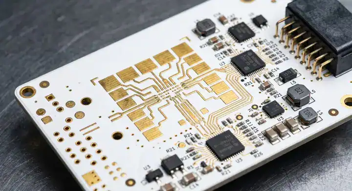
Quick Answer: RT/duroid 5880 is a woven-glass reinforced PTFE high-frequency laminate featuring the market’s lowest Dk of 2.20 and a Df of 0.0009. This exceptionally low Dk maximizes patch antenna physical dimensions by 17% compared to Dk 3.00 materials, resulting in significantly higher antenna gain for 77 GHz radar and aerospace applications. Total manufacturing costs run approximately 3.8× higher than standard FR-4 due to mandatory plasma desmear and specialized PTFE drilling requirements. Key takeaways:
- Delivers the lowest dielectric constant (Dk 2.20) available in copper-clad laminates.
- Requires FEP bonding films at 315°C for hybrid stackups.
- Unmatched for space-qualified outgassing (NASA TML < 0.05%).
- Astra MT77 can replace it in cost-sensitive applications not requiring Dk < 2.5.
Designing phased array radar systems or satellite payloads brings a specific set of physics limitations, especially when signal loss and antenna gain dictate mission success. You might find your current substrate forcing your antenna elements to be too small, killing your gain at 77 GHz. The solution to maximizing radiation efficiency is lowering the dielectric constant of your substrate. This RT/duroid 5880 PCB guide explains how this specific PTFE material solves high-frequency design constraints.
Table of Contents
- Why Does RT/duroid 5880 at Dk 2.20 Remain Unmatched After 50 Years?
- How Do RT/duroid 5880 and 5880LZ Differ for Aerospace Applications?
- What Electrical and Thermal Properties Define This Woven Glass PTFE?
- Which Satellite, Radar, and Military Designs Depend on Dk 2.20?
- How Does This Laminate Compare to RO3003 and Astra MT77?
- Where Does It Sit in the Full Rogers RF Portfolio?
- How Do You Build a High-Frequency PTFE + FR-4 Hybrid Stackup?
- What Does It Really Cost to Process RT/duroid 5880 on a PTFE Line?
- When Can You Replace This Substrate with Astra MT77 to Save Money?
- How Will 6G and Sub-THz Frequencies Push Dk 2.20 to Its Limits?
- FAQ
Why Does RT/duroid 5880 at Dk 2.20 Remain Unmatched After 50 Years?
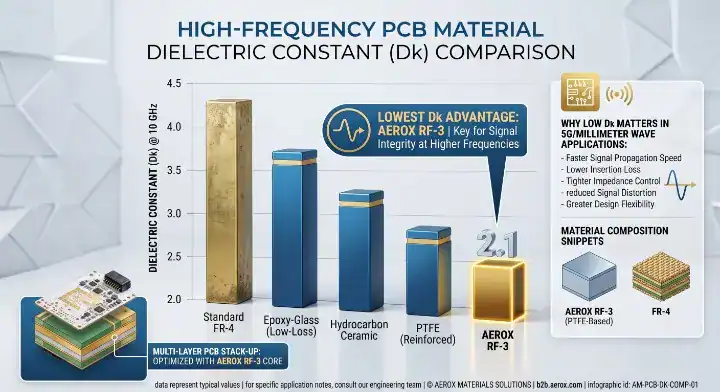
RT/duroid 5880 remains the industry standard because its Dk of 2.20 is the absolute lowest value available for copper-clad laminates on the commercial market. Patch antenna size is inversely proportional to the square root of the dielectric constant (Dk). By using Dk 2.20, your physical antenna elements grow 17% larger than they would on a Dk 3.00 material. Larger physical antennas directly translate to higher radiation gain and wider bandwidth.
Users on the EEVBlog Forum frequently ask: “Why is 5880 still used when newer materials like Astra MT77 exist?” The answer lies purely in antenna physics and signal propagation speed. Signal velocity scales with 1/√Dk, making signals travel 17% faster on this substrate compared to RO3003.
The Physics of Minimum Dispersion
Here is the reality behind its longevity:
- Dispersion control: Dk 2.20 remains incredibly flat from DC to 110 GHz, preventing pulse distortion.
- Impedance matching: Lower Dk allows wider microstrip traces for 50-ohm lines, reducing manufacturing tolerance sensitivity.
- Wavelength scaling: At 77 GHz, a larger physical wavelength on the board makes fabrication possible.
Key Takeaway: Bottom line: Specify RT/duroid 5880 when you need to physically enlarge your mmWave patch antennas to achieve maximum radiation gain.
| Feature | RT/duroid 5880 | Higher Dk Materials (e.g., Dk 3.00) |
|---|---|---|
| Patch Antenna Size | 100% (Baseline) | 83% (17% smaller) |
| Signal Speed | 100% (Baseline) | 83% (17% slower) |
| Trace Width for 50Ω | Wider | Narrower |
Analysis: The physics of Dk 2.20 cannot be replicated by chemistry; you either have the lowest Dk or you compromise on antenna size.
How Do RT/duroid 5880 and 5880LZ Differ for Aerospace Applications?
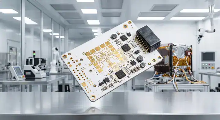
RT/duroid 5880LZ is a specialized lightweight variant that cuts the standard material density by 38%, dropping from 2.20 g/cm³ down to 1.37 g/cm³. The LZ version achieves an even lower Dk of 1.96 by utilizing a proprietary low-density filler instead of standard micro-fiberglass. While standard 5880 excels in general high-frequency RF, the LZ variant specifically targets aerospace payloads where every gram impacts launch costs.
Weight Reduction vs Structural Integrity
Consider the trade-offs when modifying the filler:
- Z-Axis CTE: The LZ version exhibits a lower Z-axis coefficient of thermal expansion, increasing plated through-hole (PTH) reliability.
- Material cost: The proprietary low-density filler makes 5880LZ significantly more expensive than the baseline material.
- Machining: Both require identical sodium naphthalene treatment, but the LZ version cuts slightly softer during routing.
Key Takeaway: Bottom line: Upgrade to RT/duroid 5880LZ exclusively for satellite or airborne platforms where strict payload weight limits justify the severe cost premium.
| Specification | RT/duroid 5880 | RT/duroid 5880LZ |
|---|---|---|
| Dk @ 10 GHz | 2.20 | 1.96 |
| Density | 2.20 g/cm³ | 1.37 g/cm³ (-38%) |
| Primary Filler | Micro-fiberglass | Low-density proprietary |
Analysis: The 38% weight reduction translates to massive fuel savings across the lifespan of a low Earth orbit (LEO) satellite.
What Electrical and Thermal Properties Define This Woven Glass PTFE?
Coefficient of Thermal Expansion (CTE) in the Z-axis is a structural metric measuring how much a substrate expands when heated, hitting a staggering 237 ppm/°C for this material. This extreme Z-axis expansion requires careful via aspect ratio management to prevent barrel cracking during assembly. Despite the poor Z-axis thermal performance, its X and Y axes remain highly stable at 31 and 48 ppm/°C due to the woven glass reinforcement.
Flammability and Space Ratings
Pay close attention to these limitations:
- UL Rating: This laminate carries a UL 94 HB rating, meaning it is not flame retardant (Not V-0).
- Moisture absorption: It absorbs virtually no water, clocking in at 0.02%, preserving RF performance in humid environments.
- Thermal conductivity: It dissipates heat poorly at 0.20 W/mK, requiring thermal vias for high-power amplifiers.
Key Takeaway: Bottom line: Never use this material in consumer electronics or automotive cabin applications that legally require a UL 94 V-0 flame retardant rating.
| Property | Value | Condition |
|---|---|---|
| Dissipation Factor (Df) | 0.0009 | @ 10 GHz |
| Z-axis CTE | 237 ppm/°C | Ambient to 288°C |
| Moisture Absorption | 0.02% | 48 hours |
Analysis: The exceptional RF performance comes with the strict engineering trade-off of a massive Z-axis thermal expansion rate.
Which Satellite, Radar, and Military Designs Depend on Dk 2.20?
Military phased array radars and LEO satellite communications rely on Dk 2.20 because it maximizes beam steering accuracy and minimizes signal loss on cross-polarized feeds. GPS anti-jamming antennas require the lowest possible Dk to maintain broad bandwidth coverage across L1, L2, and L5 bands simultaneously. While commercial telecommunications use alternatives outlined in our 5G base station PCB material selection guide, defense applications accept no compromises on antenna physics.
A Ka-Band Satellite Case Study
Our highest-profile RT/duroid 5880 build was a 4-layer Ka-band satellite LNB feed network for a LEO constellation customer. The board used two 5880 core layers at 10 mil for the 20 GHz receive and 30 GHz transmit feed networks. These were bonded with FEP film to two thin FR-4 layers carrying the DC bias and control circuitry.
The critical specification was insertion loss: the customer required < 0.15 dB total loss on the 30 GHz transmit path across a 2.5-inch microstrip feed. Our coupon measurement came in at 0.054 dB/inch at 30 GHz, resulting in a total path loss of 0.135 dB. The customer also required NASA-grade outgassing data (TML < 0.05%), which this laminate passes effortlessly.
Key Takeaway: Bottom line: Rely on this PTFE formulation for space-bound hardware because no thermoset material can guarantee NASA-qualified outgassing performance.
| Application | Primary Reason for Dk 2.20 | Viable Alternative |
|---|---|---|
| Military Phased Arrays | Maximum antenna gain | None |
| Satellite LNB/LNA | Minimum noise figure + Outgassing | None for space use |
| GPS Anti-jam | Wideband L1/L2/L5 coverage | None |
Analysis: Defense and space sectors prioritize raw physics over fabrication costs, cementing this material’s position in mission-critical hardware.
How Does This Laminate Compare to RO3003 and Astra MT77?
RT/duroid 5880 utilizes woven glass micro-fibers for mechanical strength, whereas RO3003 relies entirely on ceramic fillers with zero glass reinforcement. A common question on Electronics Stack Exchange addresses this exact difference: “What’s the real difference between RT/duroid 5880 and RO3003?” The woven glass gives 5880 superior dimensional stability during fabrication, but RO3003 delivers slightly better passive intermodulation (PIM) performance due to the lack of glass-to-resin boundaries.
The Thermoset Alternative
Consider the fundamental chemistry shift:
- RO3003 vs 5880: For detailed processing insights, see our Rogers RO3003 ceramic PTFE processing guide.
- Astra MT77: This is a thermoset resin, not PTFE. It processes exactly like standard FR-4 without requiring plasma desmear.
- Df Comparison: 5880 (0.0009) beats RO3003 (0.0010) and significantly outperforms Astra MT77 (0.0017).
Key Takeaway: Bottom line: Choose 5880 for physical strength and Dk 2.20, but pivot to Astra MT77 when your budget restricts the high costs of PTFE processing.
| Metric | RT/duroid 5880 | RO3003 | Astra MT77 |
|---|---|---|---|
| Dk Value | 2.20 | 3.00 | 3.00 |
| Base Chemistry | PTFE | PTFE | Thermoset |
| Glass Reinforcement | Yes | No | Yes |
Analysis: The presence of woven glass makes handling thin 5880 cores significantly easier for fabricators than handling unreinforced RO3003.
Where Does It Sit in the Full Rogers RF Portfolio?
Within the Rogers portfolio, RT/duroid 5880 occupies the absolute top tier for high-frequency, low-loss performance, specifically dominating the 77 GHz to 110 GHz spectrum. Below this tier sits the RO3000 series, which offers a balance of ceramic PTFE performance at a lower price point for commercial millimeter-wave. Further down sits the thermoset RO4000 series, which sacrifices raw dielectric performance for standard FR-4 manufacturability.
Cost vs Performance Hierarchy
Map out your material budget:
- Tier 1 (Ultimate RF): RT/duroid series offers Dk 2.20 but demands strict PTFE processing.
- Tier 2 (Commercial mmWave): RO3000 series provides excellent Df but poses dimensional stability challenges.
- Tier 3 (Sub-6 GHz / Easy Processing): Review the RO4350B specifications and RF design considerations to see why thermosets rule the high-volume market.
Key Takeaway: Bottom line: Position 5880 strictly at the pinnacle of your hardware designs, using it only when RO4000 or RO3000 series fail your insertion loss budgets.
| Rogers Series | Primary Material | Target Market | Relative Cost |
|---|---|---|---|
| RT/duroid 5000 | Woven Glass PTFE | Military / Space | $$$$ |
| RO3000 | Ceramic PTFE | Automotive Radar | $$$ |
| RO4000 | Hydrocarbon Thermoset | 5G Sub-6 GHz / Wi-Fi | $$ |
Analysis: Rogers segments their materials perfectly; paying the PTFE premium is only justified when thermosets physically cannot meet the target frequency requirements.
How Do You Build a High-Frequency PTFE + FR-4 Hybrid Stackup?
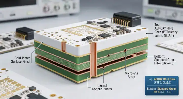
FEP bonding film is a thermoplastic adhesive required to laminate PTFE cores to standard FR-4 layers in a hybrid stackup. Engineers on Reddit often struggle with this process, asking: “How do I bond RT/duroid 5880 to FR-4?” You absolutely cannot use standard FR-4 prepreg (like 1080 or 2116) placed directly against the PTFE core because the low surface energy of Teflon prevents chemical adhesion, guaranteeing immediate delamination.
The 315°C Lamination Challenge
Here is the reality of hybrid fabrication:
- Extreme Temperatures: FEP bonding requires a press cycle reaching 315°C to melt the thermoplastic film.
- FR-4 Survival: The FR-4 layers in the stackup must withstand this 315°C spike without resin degradation or pad cratering.
- Alternative Adhesives: Rogers 2929 adhesive can be used at lower temperatures, but FEP provides the most reliable mmWave electrical match.
Key Takeaway: Bottom line: Specify high-Tg FR-4 (Tg > 170°C) for the digital layers to survive the brutal 315°C FEP lamination cycle required by the PTFE cores.
| Layer Type | Material | Function |
|---|---|---|
| L1 – L2 (RF) | RT/duroid 5880 (10 mil) | 77 GHz Antenna Feed |
| Bonding | FEP Film (1-2 mil) | Thermoplastic Adhesion |
| L3 – L4 (Digital) | High-Tg FR-4 | Power / Control Logic |
Analysis: Hybrid builds localize the expensive PTFE exactly where the RF signal lives, slashing overall board material costs by up to 40%.
What Does It Really Cost to Process RT/duroid 5880 on a PTFE Line?
RT/duroid 5880 is the most expensive material we process on a per-panel basis because the fabrication chain demands aggressive chemical modifications. Discussions on All About Circuits Forum highlight confusion over these costs, as the raw laminate price isn’t astronomically higher than ceramic PTFE. The true cost originates from our mandatory sodium naphthalene hole-wall treatment at $650 per lot. Plasma desmear follows immediately, adding another $1,400 per lot to the baseline production cost.
Tool Wear and Total Financial Impact
Consider the mechanical wear on factory equipment:
- Drill bits: We use PTFE-specific drill bits at $42 each that last approximately 500-600 hits, compared to 2,200 hits on standard carbide bits.
- Etching chemistry: PTFE’s low surface energy resists standard aqueous processes, requiring specialized chemical monitoring.
- Total multipliers: Total processing cost on a 6-layer 5880 radar board runs approximately 3.8× what the same construction costs on a thermoset.
A recent 77 GHz phased array antenna panel cost $195 per unit on RT/duroid 5880 versus $72 on Astra MT77. The customer accepted this 171% premium because their phase shifter required Dk ≤ 2.25. For full fabrication capabilities, review our PTFE and RF PCB manufacturing services.
Key Takeaway: Bottom line: Budget for a 300% to 400% cost multiplier over standard FR-4 when engaging a factory for pure PTFE fabrication.
| Cost Factor | Astra MT77 (Thermoset) | RT/duroid 5880 (PTFE) |
|---|---|---|
| Hole Prep | Standard Desmear | Sodium Naphthalene ($$$) |
| Drill Bit Life | 2,200 hits | 500 hits ($$$) |
| Lamination Temp | 190°C | 315°C with FEP ($$$) |
Analysis: Factory processing costs outweigh the raw material premium; you are paying for the time and specialized chemicals required to tame Teflon.
When Can You Replace This Substrate with Astra MT77 to Save Money?
On SierraConnect, designers ask: “When can I switch from RT/duroid 5880 to Astra MT77 and save money?” The honest answer is: any time your design doesn’t require a Dk below 2.5 or NASA outgassing qualification. That covers roughly 60% of the commercial RF boards we evaluate. The 28 GHz 5G AAU market has already largely shifted because Astra MT77 at Dk 3.00 delivers perfectly acceptable insertion loss on feed networks under 4 inches.
The 77 GHz Automotive Radar Split
Watch how the automotive tier-1 suppliers manage this:
- Antenna Feeds: Cost-sensitive automotive 77 GHz antenna feed networks are rapidly migrating away from PTFE.
- LNA Stages: Low Noise Amplifier first stages and precision phased array panels stay on 5880 because noise figure sensitivity demands Df ≤ 0.0010.
- Cost Reductions: Switching yields a 55% total cost reduction, validating Astra MT77 as a cost-effective alternative to PTFE.
Key Takeaway: Bottom line: Downgrade to Astra MT77 immediately if your mmWave traces are short and your antenna design can tolerate a Dk of 3.00.
| Application | Material Choice | Cost Savings |
|---|---|---|
| 28 GHz 5G AAU | Astra MT77 | ~55% reduction |
| 77 GHz Radar Feed (< 3 inch) | Astra MT77 | ~60% material savings |
| Space-Qualified Satellite LNB | RT/duroid 5880 | None (Mandatory) |
Analysis: Commercial engineering is about finding the point of “good enough.” Astra MT77 provides “good enough” mmWave performance at half the financial burden.
How Will 6G and Sub-THz Frequencies Push Dk 2.20 to Its Limits?
As research pushes into W-band (77-110 GHz) and D-band (110-170 GHz) for 6G networks, even the Df 0.0009 loss tangent of this substrate begins to show measurable attenuation. At these sub-THz frequencies, the copper foil roughness overtakes the dielectric material as the primary source of insertion loss. Skin effect forces the RF signal into the microscopic peaks and valleys of the copper tooth, increasing the electrical path length drastically.
Managing Copper Roughness
Consider the mechanics of sub-THz signal flow:
- Rolled Annealed Copper: Utilizing RA copper instead of Electrodeposited (ED) copper minimizes the tooth profile.
- Micro-fiberglass weave: The woven glass bundles in 5880 can cause localized Dk variations (glass weave effect) at 110 GHz.
- Future Alternatives: Liquid Crystal Polymer (LCP) may challenge PTFE in the 150 GHz range due to better copper adhesion profiles.
Key Takeaway: Bottom line: Mandate Rolled Annealed (RA) copper foil when using this laminate above 77 GHz to prevent skin effect losses from destroying your signal integrity.
| Frequency Band | Primary Loss Contributor | Required Foil Type |
|---|---|---|
| 28 GHz (5G) | Dielectric Loss (Df) | Standard ED Copper |
| 77 GHz (Radar) | Mixed (Df + Copper) | Low Profile ED Copper |
| 110+ GHz (6G) | Copper Roughness | Rolled Annealed (RA) Copper |
Analysis: At sub-THz frequencies, the laminate acts merely as a carrier; the extreme smoothness of the copper interface dictates system success.
FAQ
Can I press RT/duroid 5880 and FR-4 together in a standard lamination cycle? No, you cannot use standard FR-4 press cycles. The PTFE core requires FEP bonding film which mandates a 315°C lamination temperature, requiring specialized high-temp press profiles.
What is the best alternative to RT/duroid 5880 for automotive radar? Astra MT77 is the best alternative. It delivers a Dk of 3.00 and Df of 0.0017, processes like standard FR-4 without plasma desmear, and cuts manufacturing costs by over 50%.
How do I know if my design requires the LZ version instead of standard 5880? Yes, you need the LZ version if your satellite or airborne payload has a strict gram-level weight budget. The LZ variant cuts material density by 38%, but comes at a significantly higher procurement cost.
Does RT/duroid 5880 meet UL 94 V-0 flammability standards? No, it only achieves a UL 94 HB rating. Because PTFE is naturally resistant to flame retardant chemical additives, you cannot use it in environments legally requiring V-0 certification.
Will standard carbide drill bits work on this PTFE material? No, standard carbide bits will smear the Teflon and have a very short lifespan. Fabricators must use specialized PTFE router bits and limit drill life to roughly 500 hits per tool to maintain hole-wall integrity.
At QueenEMS, we understand the financial and technical pressures of launching high-frequency RF systems. Whether you need precise 77 GHz patch antennas on pure PTFE or cost-reduced Astra MT77 hybrid stackups, our engineering team provides free DFM reviews to prevent costly material mismatch errors before fabrication begins. To discuss your next mmWave prototype, contact us today.
Written by the QueenEMS Engineering Team
Upload your files today · Free DFM check before production · Ship worldwide
Get your PCB prototypes in as fast as 24 hours. We handle FR4, Rogers, and Flex up to 60 layers — free prototypes for 2–4 layer boards, no minimum order.
Just upload your Gerber + BOM — we source every part, assemble, and inspect (AOI + X‑Ray) so you don't have to chase suppliers. Boards ship in as fast as 24 hours.