
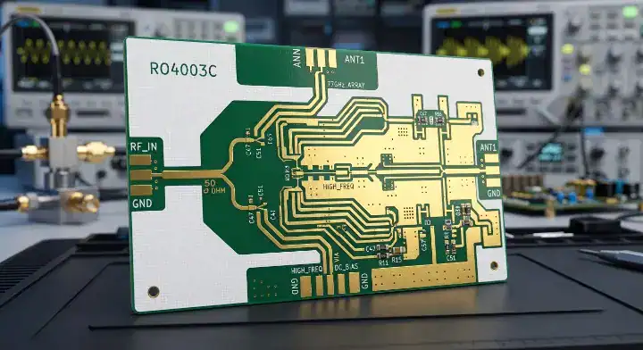
Quick Answer: RO4003C is a hydrocarbon ceramic laminate featuring a Df of 0.0027, which is 27% lower than its sister material RO4350B. The critical difference is that it lacks a UL 94 V-0 flame retardant rating, making it the superior choice for high-frequency applications like 5G and radar where UL certification is not legally mandated. Process Dk sits at 3.38, but engineers must use the design Dk of 3.55 to avoid impedance mismatches exceeding 6%. Key takeaways:
For the wider material-selection picture, including laminate properties, process constraints, and substitution risks, see our PCB materials guide.
- Offers a 27% lower dissipation factor (Df) compared to RO4350B.
- Lacks brominated flame retardants, making it completely halogen-free.
- Processes identically to standard high-Tg FR-4 without plasma desmear.
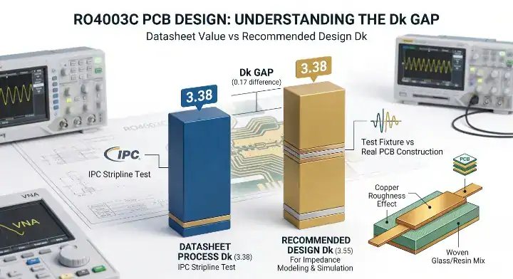
- Requires you to model impedance using a design Dk of 3.55, not the 3.38 datasheet value.
Designing high-frequency RF systems forces engineers into a tight corner when balancing signal loss against safety certifications. You might find your current substrate meets flammability standards but introduces too much attenuation for your 5G small cell. The solution lies in stripping away unnecessary chemical additives. This guide explains why utilizing RO4350B Dk trap avoidance and specifications principles applies equally to RO4003C, allowing you to solve insertion loss budgets when UL 94 V-0 is not required.
Table of Contents
- What Makes RO4003C the Non-Flame-Retardant Sibling to RO4350B?
- Why Does the Process Dk Trap Hit Impedance Designs?
- How Does RO4003C Compare to RO4350B on Key Specifications?
- Which 5G, Radar, and IoT Applications Fit This Laminate Best?
- How Does the UL 94 V-0 Rating Decision Work in Practice?
- Where Does This Substrate Sit in the Rogers RF Portfolio?
- How Does This Material Compare to Astra MT77 Above 28 GHz?
- How Do Factories Process This on the Same Line as RO4350B?
- How Do You Build a Reliable Hybrid Stackup with FR-4?
- When Is This Lower Loss Material the Wrong Choice for RF?
- FAQ
What Makes RO4003C the Non-Flame-Retardant Sibling to RO4350B?
RO4003C is a non-brominated, woven-glass reinforced hydrocarbon resin system delivering a dielectric constant (Dk) of 3.38 and a dissipation factor (Df) of 0.0027. It shares the exact same base chemistry as RO4350B but omits the flame-retardant additives, dropping the loss tangent by 27%.
The Halogen-Free Advantage
Understanding chemical compliance helps avoid regulatory redesigns later:
- Halogen-free compliance is a regulatory standard restricting bromine and chlorine content to under 900 ppm. Because this laminate skips brominated flame retardants entirely, which means it eliminates restricted halogens, resulting in effortless compliance with strict European RoHS requirements.
- Resin System: The hydrocarbon ceramic formulation provides extreme rigidity compared to pure PTFE materials.
- Thermal Performance: It maintains a glass transition temperature (Tg) exceeding 280°C, surviving multiple lead-free reflow cycles.
Key Takeaway: Bottom line: Specify this substrate over RO4350B when your product classification allows you to skip UL 94 V-0 certification to achieve superior RF performance.
| Property | Specification | Implication |
|---|---|---|
| Dk (Process) | 3.38 ±0.05 | Consistent phase matching |
| Df @ 10 GHz | 0.0027 | Ultra-low signal attenuation |
| Halogen Content | Free (Non-brominated) | RoHS compliant globally |
Analysis: Removing the flame retardant fundamentally improves the electrical purity of the dielectric, maximizing raw RF efficiency.
Why Does the Process Dk Trap Hit Impedance Designs?
The process Dk trap occurs because the datasheet value of 3.38 is measured using a clamped stripline fixture that does not reflect real-world manufacturing conditions. Engineers must use the recommended design Dk of 3.55 to achieve accurate impedance targeting.
Real-World Fabrication Errors
The process Dk trap works exactly like its flame-retardant sibling, and catches the same engineers. Datasheet says 3.38, but Rogers recommends 3.55 for design. Our internal coupon data shows 3.43-3.47 depending on copper roughness and resin content.
Last month a customer sent us a 50 Ω microstrip design modeled at Dk 3.38. Our impedance coupons measured 53.2 Ω — a 6.4% error that would have failed IPC Class 3 tolerance (±5%). We recalculated using our measured process Dk of 3.45, adjusted the trace width from 11.2 mil to 10.6 mil, and the respin measured 50.3 Ω — dead center.
Here is the reality of impedance modeling:
- Datasheet vs Design: Never build trace models using the clamped stripline test value.
- Factory Testing: Always ask your factory for their measured internal Dk based on the specific copper foil type you select.
Key Takeaway: Bottom line: Never use the 3.38 datasheet value in your impedance solver; request the internal process Dk from your factory to prevent a 6% impedance shift.
| Metric | Dk Value | Use Case |
|---|---|---|
| Datasheet Dk | 3.38 | Material comparison only |
| Design Dk | 3.55 | Initial impedance simulation |
| Factory Process Dk | 3.43 – 3.47 | Final production CAM adjustments |

Analysis: The discrepancy is not a material defect; it represents the physical gap between laboratory testing and microstrip etching physics.
How Does RO4003C Compare to RO4350B on Key Specifications?
When comparing these two Rogers laminates, the only functional differences are the UL 94 rating, the Df (0.0027 vs 0.0037), and the Z-axis CTE (46 vs 32 ppm/°C). They process identically in the factory and offer the same Tg of >280°C.
Analyzing the Data Sheet Differences
Users on the EEVBlog Forum frequently ask: “Should I use RO4003C or RO4350B for my 5G antenna design?” The answer is strictly dependent on your UL requirements. If V-0 is not required, the 0.0027 Df provides significantly better insertion loss.
Key Takeaway: Bottom line: You are trading a UL 94 V-0 rating for a 27% reduction in signal loss and a slightly lower per-sheet material cost.
| Specification | RO4003C | RO4350B |
|---|---|---|
| Dk (Process) | 3.38 | 3.48 |
| Df @ 10 GHz | 0.0027 | 0.0037 |
| UL 94 Rating | Not Rated | V-0 |
| Z-Axis CTE | 46 ppm/°C | 32 ppm/°C |
Analysis: The choice between the two materials is binary; you either need the flammability rating or you need the absolute lowest signal loss.
Which 5G, Radar, and IoT Applications Fit This Laminate Best?
This substrate dominates 5G sub-6 GHz base station antennas, 24 GHz industrial radar sensors, and IoT RF modules where manufacturing costs must remain low. It provides a stable TCDk of 40 ppm/°C, ensuring consistent phase performance across massive MIMO arrays.
Application Routing and Compliance
Reviewing a halogen-free PCB specification and manufacturing rules guide helps identify the environmental advantages. When consumer safety ratings do not dictate the build, this laminate outperforms standard alternatives.
Many designers consult a 5G base station PCB material selection guide to understand why thermosets dominate telecom.
- 24 GHz Radar: The 0.0027 loss tangent easily supports short-range industrial and automotive blind-spot sensors.
- Massive MIMO: Large antenna panels require exceptional dimensional stability, which the woven glass reinforcement provides perfectly.
Key Takeaway: Bottom line: Deploy this material for permanent industrial or military installations where performance outweighs consumer safety classifications.
| Application | Fit Level | Primary Reason |
|---|---|---|
| 5G Sub-6 Antennas | Excellent | Low loss + high stability |
| 24 GHz Radar Sensors | Excellent | Df 0.0027 handles the frequency |
| Consumer WiFi Routers | Poor | Lacks required UL 94 V-0 |
Analysis: Telecommunications hardware stationed on outdoor towers rarely requires V-0 ratings, making this substrate the undisputed volume leader.
How Does the UL 94 V-0 Rating Decision Work in Practice?
Determining if your product requires a UL 94 V-0 rating depends entirely on the end-use environment and target market regulations. Consumer electronics generally mandate V-0, while permanently connected industrial equipment often accepts materials that are not rated.
The Decision Matrix
A recent customer came to us with a 5G small cell radio board originally designed on an 8-layer RO4350B UL 94 V-0 flame-retardant RF laminate hybrid stackup. The product compliance team confirmed the small cell did not require UL 94 V-0 certification because it was classified as permanently connected industrial equipment.
We proposed switching the RF layers to the lower-loss sibling. After resimulating trace widths for the Dk shift (3.66 design to 3.55 design) and running a prototype, the new build measured 0.16 dB/inch insertion loss at 10 GHz versus 0.19 dB/inch previously — a 16% improvement. On their 2,000-unit production run, the combined savings from lower material costs and eliminating a 1 dB compensation gain pad totaled approximately $12,000.
Engineers on Reddit ask: “How do I know if my product needs UL 94 V-0?” You must check your specific market regulations early in the design phase.
Key Takeaway: Bottom line: Consult your compliance team early; switching to this non-rated laminate can yield measurable cost and performance benefits.
| Market Sector | Typical UL 94 Requirement | Material Recommendation |
|---|---|---|
| Consumer Electronics | Mandatory (V-0) | RO4350B |
| Industrial / IoT | Optional | RO4003C |
| Military / Aerospace | MIL-STD overrides UL | RO4003C |
Analysis: Regulatory classifications dictate your material choice long before physics calculations begin; never assume V-0 is mandatory for every project.
Where Does This Substrate Sit in the Rogers RF Portfolio?
Within the Rogers hierarchy, this material sits at the top of the hydrocarbon thermoset tier, offering the lowest loss before upgrading to pure PTFE. It bridges the gap between standard FR-4 and expensive aerospace-grade laminates.
Navigating the Material Tiers
Engineers often transition from this substrate straight to a Rogers RO3003 PTFE processing guide when frequencies surpass 60 GHz.
- The Thermoset Limit: This is the absolute best electrical performance you can get from Rogers without introducing complex plasma desmear processes.
- Cost Efficiency: It delivers 85% of PTFE performance at a fraction of the raw material and fabrication cost.
Key Takeaway: Bottom line: Exhaust the capabilities of this Df 0.0027 thermoset before authorizing the massive budget increase required for PTFE.
| Material Series | Base Chemistry | Df @ 10 GHz | Fabrication Difficulty |
|---|---|---|---|
| FR-4 (High-Tg) | Epoxy | 0.0150 | Low |
| RO4003C | Hydrocarbon | 0.0027 | Low |
| RO3003 | Ceramic PTFE | 0.0010 | High |
Analysis: Rogers specifically engineered this material to provide near-PTFE electrical characteristics while maintaining standard FR-4 mechanical processing ease.
How Does This Material Compare to Astra MT77 Above 28 GHz?
Above 28 GHz, Astra MT77 offers a superior Df of 0.0017 compared to 0.0027, making it better for long millimeter-wave antenna feeds. However, the Rogers material provides better thermal conductivity at 0.71 W/mK versus 0.40 W/mK for high-power amplifiers.
Balancing Loss and Heat
Discussions on SierraConnect debate: “Between RO4003C and Astra MT77, which is better for 28 GHz?” The answer depends entirely on your thermal load and signal path length.
A comprehensive Astra MT77 non-PTFE mmWave laminate guide shows how Isola competes aggressively in this space.
- Thermal Management: Power amplifier (PA) stages require high thermal conductivity to pull heat away from active components.
- Insertion Loss: Passive antenna arrays with long feed lines benefit drastically from dropping Df down to 0.0017.
Key Takeaway: Bottom line: Select Astra MT77 for pure millimeter-wave antenna arrays, but retain the Rogers substrate for power amplifier stages that run hot.
| Metric | Rogers Laminate | Astra MT77 |
|---|---|---|
| Df @ 10 GHz | 0.0027 | 0.0017 |
| Thermal Conductivity | 0.71 W/mK | 0.40 W/mK |
| UL 94 Rating | Not Rated | V-0 |
Analysis: Advanced 5G AAU designs frequently mix both materials, deploying Rogers near the heat sinks and Isola on the radiating patches.
How Do Factories Process This on the Same Line as RO4350B?
Fabricators process both materials on the exact same production line using identical 190°C lamination cycles and mechanical drill parameters. The woven glass reinforcement allows it to process much closer to standard FR-4 than soft PTFE materials.
Factory Floor Realities
We process both siblings on the exact same fabrication line — same lamination press, same etch chemistry, same drill parameters, and same impedance test equipment. The materials are mechanically identical under our tooling.
Drill bit life runs within 5% between the two (approximately 2,400 hits on the non-rated material versus 2,300 hits on the V-0 version). The only visible difference in our process data is impedance. On the same 5 mil, 50 Ω microstrip construction, the non-rated version measures approximately 2.0-2.5 Ω higher impedance because of the lower Dk (3.38 vs 3.48 process). You cannot swap one for the other without resimulating trace widths.
For a complete breakdown of factory capabilities, review our RF and high-frequency PCB manufacturing services.
Key Takeaway: Bottom line: Expect no fabrication premium over its flame-retardant sibling, as it requires no plasma desmear or specialized hole-wall preparation.
| Processing Step | Parameter | Difficulty vs FR-4 |
|---|---|---|
| Drill Bit Life | ~2,400 hits | Similar |
| Lamination Temp | 190°C | Identical |
| Hole Wall Prep | Standard Desmear | Identical |
Analysis: The factory does not care which of the two variants you select; the manufacturing cost footprint is virtually indistinguishable.
How Do You Build a Reliable Hybrid Stackup with FR-4?
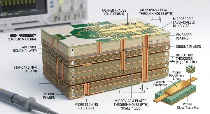
Hybrid stackups combine thin high-frequency RF cores with standard high-Tg FR-4 digital layers to reduce overall board cost by up to 40%. The hydrocarbon resin system in this material bonds flawlessly with standard FR-4 prepregs like 1080 and 2116.
Lamination Cycles and Adhesion
Because it uses a thermoset resin system, which means it doesn’t require extreme thermoplastic melting points, resulting in standard 190°C pressing compatibility alongside standard epoxy layers.
- Prepreg Selection: High-Tg FR-4 prepregs (Tg > 170°C) are recommended for multi-lamination cycles.
- Dimensional Stability: The woven glass reinforcement prevents misregistration between the RF layer and the digital core during pressing.
Key Takeaway: Bottom line: Localize your expensive RF material exclusively on layers 1 and 2, utilizing FR-4 for the remaining digital and power planes.
| Layer | Material Type | Primary Function |
|---|---|---|
| L1 – L2 | High-Frequency Core | RF signal routing |
| Prepreg | Standard High-Tg FR-4 | Bonding agent |
| L3 – L6 | Standard FR-4 Core | Power and digital logic |
Analysis: Hybrid architectures maximize your return on investment by deploying premium dielectrics only where the physics demand them.
When Is This Lower Loss Material the Wrong Choice for RF?
This laminate is the wrong choice when your design requires a dielectric constant below 3.00, mandates strict UL 94 V-0 compliance, or operates in deep space environments requiring NASA outgassing certification.
Hard Limits of Hydrocarbon
A common question on Electronics Stack Exchange is: “Can I use this for satellite LNBs?” No, space-bound hardware typically requires the extreme low loss and strict outgassing guarantees of pure PTFE.
- Millimeter-Wave Radar: At 77 GHz, the 0.0027 Df introduces too much attenuation for high-gain phase shifters.
- Space Payloads: It lacks NASA TML < 0.05% outgassing certification out of the box.
Key Takeaway: Bottom line: Pivot to RT/duroid 5880 for mission-critical aerospace payloads, as thermoset resins cannot match the raw physics of Dk 2.20.
| Restriction | Reason | Required Alternative |
|---|---|---|
| V-0 Mandatory | Lacks flame retardant | RO4350B |
| > 77 GHz Gain | Df too high | RT/duroid 5880 |
| Space Flight | Outgassing risks | PTFE Laminates |
Analysis: Pushing a material beyond its intended frequency band results in massive signal degradation; know exactly when to upgrade your chemistry.
FAQ
Should I choose RO4003C or RO4350B for my project? Yes, use the V-0 rated version if consumer regulations require it. However, if your product is classified for industrial use where V-0 is not mandated, switch to the non-rated sibling to gain a 27% reduction in dielectric loss.
Should I use process Dk 3.38 or design Dk 3.55 for impedance modeling? Always use the design Dk of 3.55 for your initial simulations. Better yet, request the actual internal measured process Dk from your fabricator, as using the 3.38 datasheet value will result in impedance errors exceeding 6%.
Is RO4003C considered a halogen-free material? Yes, it is entirely non-brominated. Because it does not contain the bromine-based chemical flame retardants found in its sister materials, it effortlessly passes strict European RoHS halogen-free compliance standards.
Does RO4003C outperform Astra MT77 at 28 GHz? No, it does not win on raw signal loss, as Astra MT77 delivers a lower Df of 0.0017. However, the Rogers material offers significantly higher thermal conductivity (0.71 W/mK), making it the better choice for hot power amplifier stages.
Can I swap RO4350B for RO4003C without redesigning traces? No, you cannot perform a direct swap. The lower dielectric constant requires you to recalculate your microstrip geometries; leaving the traces identical will shift your target 50-ohm line up by approximately 2.0 to 2.5 ohms.
At QueenEMS, we understand that selecting the exact right dielectric directly dictates your hardware margins. Whether you need impedance-controlled hybrid stackups or fully documented 5G small cell prototypes, our engineering team provides free process Dk calculations to eliminate simulation errors before fabrication. To review your next RF design, contact us today.
Written by the QueenEMS Engineering Team
Upload your files today · Free DFM check before production · Ship worldwide
Get your PCB prototypes in as fast as 24 hours. We handle FR4, Rogers, and Flex up to 60 layers — free prototypes for 2–4 layer boards, no minimum order.
Just upload your Gerber + BOM — we source every part, assemble, and inspect (AOI + X‑Ray) so you don't have to chase suppliers. Boards ship in as fast as 24 hours.