

Quick Answer: Compare the PTH aspect ratio in each supplier quotation only after each supplier identifies the hole diameter, drilled span and thickness convention behind its number. A ratio calculated from a mechanical drill diameter can differ from one based on the finished bore. Reconcile those dimensions and the proposed construction before accepting a manufacturing quotation.
A feasibility reply that says “10:1 accepted” looks decisive until another supplier calculates a different ratio from the same drawing. Both calculations may be internally consistent. The purchasing problem is identifying which physical hole each reply describes. This guide addresses mechanically drilled plated through holes, including deep holes in complex multilayers. It keeps laser microvia design and detailed plating-report acceptance with their separate engineering reviews.
What does a PTH aspect ratio number describe?
A PTH aspect ratio expresses hole depth relative to a stated diameter. For a manufacturing comparison, identify whether that diameter means the mechanical drill or the finished plated bore, and whether depth means the completed board or a drilled subassembly. Keep the numerator and denominator attached to the quoted value.
Altium’s aspect ratio explanation, updated in July 2024, defines the calculation as drill depth divided by drill diameter. Other published fabrication guidance uses finished-hole diameter. A purchasing specification should therefore name its convention explicitly and ask suppliers to explain any different convention in their replies.
The distinction is physical. The drill creates an opening; subsequent processing produces the specified finished hole. A component lead or press-fit contact engages that finished opening. The manufacturer must establish the tool and process needed to produce it. A designer’s finished-hole callout should remain the functional requirement while the supplier returns its manufacturing interpretation.
Depth also needs a physical boundary. A through hole drilled through a completed stack crosses that stack. A connection drilled and plated in a subassembly before later lamination belongs to a different manufacturing stage. Record the thickness of the part at the actual drilling stage beside its layer span. The supplier can then identify which stack is being assessed.
Record units and tolerances with these dimensions. A nominal value supports a nominal calculation; a maximum-thickness check needs the corresponding thickness condition. Neither result establishes a supplier’s production capability. The useful output is a defined geometry that the fabricator can accept, question or replace with an identified proposal.
Why can two quotations give different ratios for the same hole?
Two quotations can use different diameter definitions or thickness conditions while displaying similar ratio labels. Recalculate each reply from its declared inputs, then compare the physical requirements. Matching numerical ratios are insufficient when one supplier describes a tool and the other describes the finished hole that your drawing requires.
Consider this hypothetical arithmetic example. A quoted drilling span is 3.2 mm and the supplier explicitly names a 0.30 mm mechanical drill. The drill-based ratio is 3.2 ÷ 0.30 = 10.67:1. This calculation describes only those assumed dimensions. It supplies no minimum wall-copper requirement and makes no statement about the resulting finished bore.
Now consider a second reply that uses 0.30 mm as the finished-hole diameter. It can report the same 10.67:1 value using the same nominal thickness, yet its mechanical tool remains unspecified. The two replies have used the same number for different physical objects. Ask for the proposed tool-to-finished-hole relationship before calling the quotations equivalent.
The direction of the difference is predictable even when its size is not. For a plated hole, the mechanical drill is normally larger than the finished bore, because copper and any surface finish are deposited on the wall. For the same physical hole, a drill-based ratio therefore prints lower than a finished-hole-based ratio. A supplier accepting “10:1 finished” has accepted a smaller drill-based ratio than one accepting “10:1 drill.” The size of that gap depends on the supplier’s process and is not assumed here.
| Illustrative reply | Declared calculation | Unresolved purchasing input |
|---|---|---|
| A: drill-based | 3.2 mm span ÷ 0.30 mm tool = 10.67:1 | How does the proposed process meet the required finished bore and tolerance? |
| B: finished-hole-based | 3.2 mm span ÷ 0.30 mm finished bore = 10.67:1 | Which mechanical tool and process does the supplier propose? |
Keep the example separate from a real order. No plating allowance has been assumed, and the table does not approve a 0.30 mm tool for a 0.30 mm finished-hole requirement. The supplier must resolve that relationship for the actual construction. Do not invent an oversize allowance merely to make the two calculations agree.
A thickness convention can create another difference. With an explicitly assumed maximum drilled thickness of 3.3 mm and the same 0.30 mm tool, the arithmetic becomes 11:1. Compare nominal with nominal and worst-case with the same stated condition. A smaller printed ratio may simply reflect a different input convention.
Which hole families need their own feasibility line?
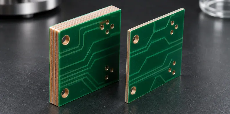
Give each mechanically drilled hole family its own line when function, finished bore, tolerance, drilling span or construction differs. A component hole, press-fit hole and via-only connection can impose different requirements even on one board. Group genuinely equivalent holes together and identify the family that drives the manufacturing review.
Start with function because it explains which dimension must survive a proposed change. A component lead needs its specified finished opening. A press-fit contact requires the hole definition agreed with the connector design. A via-only hole may permit a different geometry if electrical, thermal and layout requirements remain satisfied. Purchasing should not authorize the same change across all three by default.
Then map each family to its drilling stage. Include start and stop layers, whether the operation occurs before or after a particular lamination, and the stack revision that defines its thickness. If a supplier proposes a shorter plated span, ask for the corresponding connection drawing. The proposal may change the interconnection architecture rather than merely improve a ratio.
Keep unplated mechanical holes identifiable as a separate family. They may need a drilling review, but they do not require the same plated-barrel definition as a PTH. If a drill export uses one nominal diameter for both functions, retain the plated or unplated designation in the comparison. Otherwise, a supplier’s reply can appear to accept a hole without identifying which finished construction it covers.
A useful family identifier follows the requirement through the drill table, fabrication drawing and supplier response. It lets an engineer identify which specific hole is accepted when a reply says “small vias require review.” Coordinate examples or a marked drill plot can locate a family without replacing its dimensional definition.
For the broader construction inquiry, see the multilayer PCB manufacturing page; attach the named hole families when you submit the stack so the supplier reviews their drilled depths and finished fits.
What makes deep mechanical holes difficult to drill and plate?
Deep, narrow mechanical holes combine drilling and hole-wall processing constraints with the need to deposit adequate copper inside the opening. Surface copper thickness alone cannot describe the entire barrel. Feasibility therefore depends on the actual hole family, material sequence and qualified process, alongside the dimensions used in the ratio.
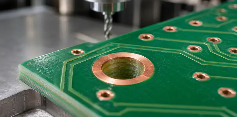
During drilling, the tool must form the specified path through the stack and remove debris without leaving unacceptable hole geometry or wall condition. The material sequence matters: a mechanically drilled hole through one uniform construction presents a different processing question from a hole crossing a mixed-material stack. Ask which construction the supplier’s response covers.
Copper deposition then has to reach the internal wall. A MacDermid study hosted by IPC describes microdistribution as the relationship between deposited copper near the hole centre and copper at the surface. Its 2009 test vehicles illustrate how process conditions and geometry affect distribution. They are historical study conditions, not current universal fabrication limits.
For purchasing, the consequence is to connect a feasibility statement with the required finished hole and wall-copper requirement. An offer of additional surface copper does not, by itself, explain coverage at the critical barrel location. The supplier should identify the construction and evidence supporting the specific proposal.
Detailed sampling, section locations and plating-report interpretation belong in the separate PCB copper plating evidence guide. Refer to that review once both quotations describe the same hole. With a common geometry established, engineering can compare the relevant inspection evidence.
How should you compare supplier replies side by side?
Compare suppliers in a shared matrix that preserves your finished requirement and records each proposed manufacturing interpretation separately. Require a disposition for every unresolved difference. This makes a quotation review actionable: engineering can see what is accepted, what changes, and which assumption still needs a supplier response before ordering.
| Comparison field | What to record for A and B | Why it affects approval |
|---|---|---|
| Hole family and function | Drawing identifier and connected feature | Keeps acceptance tied to the intended holes |
| Finished bore | Required diameter, tolerance and drawing revision | Preserves component fit or via function |
| Tool basis | Supplier’s proposed mechanical diameter or unresolved status | Separates manufacturing input from finished requirement |
| Span and stage | Drilled layers and manufacturing stage | Identifies the physical depth being assessed |
| Thickness condition | Nominal or maximum, with applicable tolerance | Explains numerator differences |
| Ratio convention | Named numerator, denominator and calculated value | Makes the arithmetic reproducible |
| Construction | Material sequence and stack revision | Defines the scope of the feasibility statement |
| Disposition | Accepted, proposed deviation or open item | Separates an offer from an approved change |
| Approval owner | Responsible engineering contact and returned revision | Closes the decision in the order package |
This is an editorial comparison aid rather than a standard form. Fill it from the drawing and actual supplier replies. Leave a tool diameter unresolved when it has not been returned. Recording an assumption as a confirmed value makes the matrix look complete while hiding the decision it was meant to expose.
Read a supplier’s “accepted” status alongside any exception notes. A reply may accept the overall board while proposing a larger finished hole for one family. Put that proposal on the family row and obtain engineering approval. A quotation’s general acceptance statement should not silently amend the drill drawing.
Close the comparison with one consistent manufacturing package. The selected quotation, marked drawing and supplier-returned stack must identify the same approved construction. Retain rejected alternatives as review history so a repeat order does not revive an earlier assumption about the hole basis.
What can change when a supplier rejects the geometry?
A geometry rejection may require a larger hole, a thinner drilled structure or a different connection span, each with consequences beyond the ratio. Ask for a specific alternative, then review the affected fit, lands, routing and stack. Approve the resulting construction rather than selecting an isolated ratio that appears easier to manufacture.
A larger mechanical tool requires reconciliation with the finished bore and surrounding copper. If the finished hole must also increase, component fit, annular geometry and nearby routing need review. The supplier’s proposal should show the changed dimension explicitly; a general request to “increase vias” is too broad for a controlled order.
A thinner structure changes the numerator but may also change mechanical engagement and the electrical stack. A shorter drilled span changes where the connection is formed. Check those consequences against the design before accepting either option. The fabricator’s feasible alternative is an input to that decision.
QueenEMS’ regular PCB range reaches 24 layers, and high-end constructions reach up to 100 layers. Those layer counts do not assign a PTH ratio to a particular material stack. Extreme parameters may be possible on prototypes; confirm production suitability for the actual construction. PCB lead time also varies with material. Send the actual thickness, hole families and drawing requirements for project-specific review.
If IPC Class 3 is an order requirement, identify it with the applicable specification and agreed evidence. QueenEMS supports IPC Class 3 requirements, while the hole geometry and inspection scope still need to be resolved for the specific order. Keep the approved finished dimensions visible in the final purchasing package.
Frequently Asked Questions
Which diameter is used for aspect ratio: drill or finished hole?
Both conventions appear in published guidance. Altium defines drill depth divided by drill diameter; a supplier may state a finished-hole-based convention. Identify the basis in each quotation and retain the required finished bore separately. Compare the complete geometry before treating the numerical values as equivalent.
Does acceptance of one 10:1 hole mean every 10:1 hole is buildable?
No. A ratio describes proportions, while actual diameters, drilling stages, material sequences and requirements can differ. Ask whether the acceptance covers your named hole family and stack revision. A capability example with another geometry leaves your proposal subject to its own feasibility review.
How does required hole-wall copper affect the aspect ratio review?
The requirement affects the proposed process and tool-to-finished-bore relationship. Its effect on the printed ratio depends on the supplier’s diameter convention. Ask for that relationship explicitly. Do not add a generic plating allowance to a finished-hole callout and assume it represents the manufacturer’s tool choice.
Is a laser microvia aspect ratio the same manufacturing question?
No. A laser microvia has its own drilled depth, diameter definitions, material and formation process. This guide addresses mechanically drilled plated through holes. Review microvias separately and avoid transferring a laser-via design rule to a deep mechanical hole merely because both calculations use a depth-to-diameter relationship.
What evidence shows that the plated hole meets the requirement?
The agreed inspection and test evidence must identify the relevant hole construction and acceptance requirements. Sections can examine local wall copper and geometry; electrical tests address their specified connections. Agree the locations, sampling and interpretation with the fabricator rather than treating a single surface reading as complete barrel evidence.
Send your released files for a quote and free DFM review.
Send stackup, board thickness and drill data for review. Distinguish finished holes from drill sizes and state the acceptance evidence needed.
For assembly, identify leaded components and press-fit parts in the BOM. Confirm finished-hole requirements and which insertion operations are requested.