
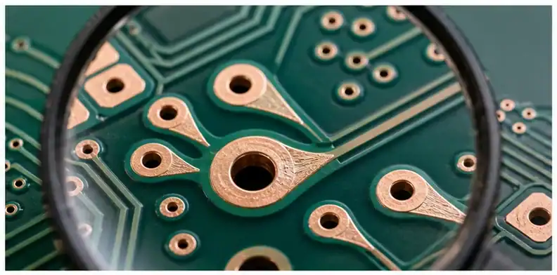
Quick Answer: Decision: teardrop CAM authorization. Controlled object: before-and-after copper comparison naming the nets, padstacks, layers, geometry limits, and exclusions for added teardrops. Design-owned boundary: protected differential pairs, RF structures, high-voltage clearances, via-in-pad features, and any customer-controlled copper geometry. Supplier discretion: teardrops on approved via or PTH transitions within the released envelope and without moving traces or pads. Stop rule: automatic addition on excluded nets, a teardrop touching other copper, or a supplier unable to reproduce the same rule on reorder.
Teardrop DFM path
- When do teardrops matter in a PCB RFQ?
- Where should teardrops be used or avoided?
- Can a supplier add teardrops during CAM?
- What inspection evidence makes sense for teardrops?
- How do teardrops affect supplier comparison?
- What should a teardrop RFQ package include?
When do teardrops matter in a PCB RFQ?
Teardrops matter when trace-to-pad or trace-to-via transitions need extra copper support against drill registration, etching variation, or small annular ring risk. The buyer should discuss them when the design uses small vias, narrow traces, dense routing, heavy manufacturing tolerance pressure, or high reliability expectations.
SERP and forum answers split into two useful buyer questions: whether teardrops are helpful and whether they are required. For most rigid PCBs, teardrops are a DFM option rather than a blanket requirement; they can help narrow trace-to-via transitions and drill-registration margin, but they do not replace annular-ring rules or Class 2/Class 3 acceptance criteria. Flex circuits, dense small-via layouts, or marginal pad geometry deserve a stricter review.
- They are most useful around vias, pads, and narrow trace entrances.
- They should support manufacturability without changing clearance rules.
- They need review when the fabricator wants to add them during CAM.
| Design condition | Buyer response |
|---|---|
| Small vias and narrow traces | Ask whether teardrops are helpful |
| Strict clearance region | Require approval before addition |
| Customer-controlled layout | Record whether CAM edits are allowed |
Bottom line: Teardrops are a DFM support feature, not a reason to hide weak design data.
Where should teardrops be used or avoided?
Teardrops are commonly used at via, pad, and trace junctions where extra copper improves transition robustness. They should be avoided or reviewed carefully in controlled impedance regions, RF paths, high-voltage spacing, fine-pitch pads, or any place where extra copper changes electrical or assembly behavior.
- Use them where drill offset could reduce the connection neck.
- Review them near impedance-controlled or RF routing.
- Avoid automatic edits that violate spacing or solder mask assumptions.
| Location | Typical rule |
|---|---|
| Via-to-trace neck | Often useful for DFM margin |
| RF or impedance trace | Requires engineering review |
| Fine-pitch land pattern | Check solder and spacing effect |
Bottom line: Add teardrops where they protect copper continuity and avoid them where they change circuit behavior.
Can a supplier add teardrops during CAM?
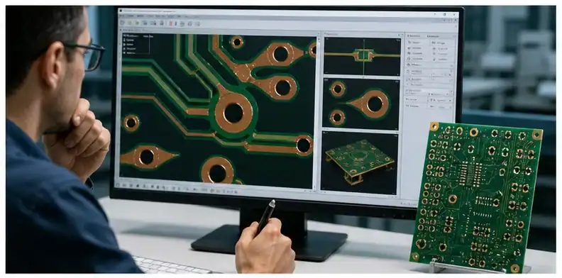
A supplier can propose teardrops during CAM, but the buyer should approve the edit when it changes released artwork. The safest approach is to define whether standard DFM teardrops are allowed, which layers or nets are excluded, and what evidence will show the final interpretation.
- Supplier-added teardrops should be visible in a marked CAM view.
- Excluded nets or regions should be listed before production release.
- Approval should come from the design owner, not only purchasing.
| CAM edit | Approval need |
|---|---|
| Standard via neck support | Often acceptable with documented rule |
| RF or impedance area | Engineering approval required |
| Clearance reduction | Do not approve without design check |
Bottom line: Supplier-added teardrops are acceptable only when the approval boundary is clear.
What inspection evidence makes sense for teardrops?
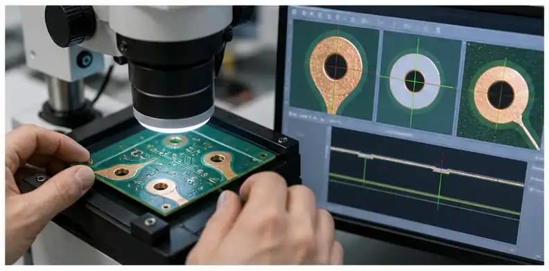
Most teardrop decisions do not need special inspection beyond normal fabrication review, but high-risk designs may need CAM screenshot approval, first-article photo, or outgoing confirmation that restricted regions were not edited. Evidence should prove the accepted DFM rule, not create paperwork for every via.
- Use marked CAM evidence for approval-sensitive edits.
- Use photo evidence for customer-facing or high-risk regions.
- Keep normal inspection scope for low-risk prototype support.
| Risk | Evidence |
|---|---|
| Allowed standard edits | CAM rule note |
| Sensitive region nearby | Marked screenshot before release |
| Customer audit | First-article or outgoing confirmation |
Bottom line: Evidence should confirm the edit boundary, not count every teardrop.
How do teardrops affect supplier comparison?
Teardrops affect supplier comparison when one factory will add DFM support and another will build strictly from supplied data. A quote that includes engineering review may be more useful than a cheaper quote that leaves marginal trace-to-pad transitions unchanged without comment.
- Ask whether DFM support is included in the quote.
- Compare supplier policy on artwork edits and approvals.
- Keep the final CAM assumption with repeat-order records.
| Supplier reply | What it means |
|---|---|
| Build as supplied | Fast but may leave marginal transitions |
| Propose DFM teardrops | Requires approval boundary |
| Rejects weak areas | May signal real capability or data risk |
Bottom line: The better quote explains the DFM policy instead of silently changing or ignoring the artwork.
What should a teardrop RFQ package include?
A teardrop RFQ package should include released PCB data, stack-up, minimum trace and via rules, controlled impedance or RF exclusions, approval policy for CAM edits, and any evidence request. QueenEMS can then review whether teardrops are useful, unnecessary, or restricted by the design intent.
- List nets or regions where extra copper is not allowed.
- State whether supplier DFM edits may be proposed.
- Use a revision record when an approved CAM view changes the artwork.
| RFQ item | Purpose |
|---|---|
| Design rule summary | Shows margin around vias and pads |
| Restricted regions | Protects RF, impedance, or clearance intent |
| CAM approval path | Prevents hidden artwork changes |
Bottom line: The RFQ should allow useful DFM help while keeping artwork ownership clear.
What should the buyer record before release?
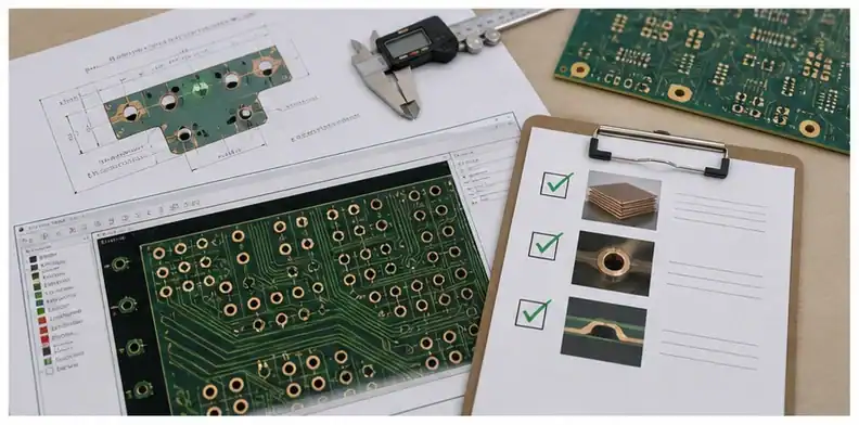
For teardrop decisions, the release record should say whether supplier-added copper support is allowed as a standard DFM edit or only after design approval. This matters for designs with RF traces, impedance rules, high-voltage spacing, or dense fine-pitch areas where extra copper can change more than manufacturability.
The buyer should also distinguish between using teardrops to improve margin and using them to hide an unsafe pad or via design. A teardrop can help with drill registration tolerance, but it should not be used as a substitute for an annular ring, clearance, or fabrication-capability review.
Production record for the teardrop CAM authorization
Controlled object
Controlled object: before-and-after copper comparison naming the nets, padstacks, layers, geometry limits, and exclusions for added teardrops.
Failure boundary
Failure boundary: changed impedance geometry, clearance violations, hidden neck-downs, unintended copper on protected nets, or inconsistent repeat builds.
Design-owned conditions
Design-owned conditions: protected differential pairs, RF structures, high-voltage clearances, via-in-pad features, and any customer-controlled copper geometry.
Supplier discretion
Supplier discretion: teardrops on approved via or PTH transitions within the released envelope and without moving traces or pads.
Required proof
Required proof: a redlined CAM comparison, rule summary, and sample inspection focused on the narrowest annular-ring or breakout condition.
Production stop
Production stop: automatic addition on excluded nets, a teardrop touching other copper, or a supplier unable to reproduce the same rule on reorder.
Repeat-order baseline
Repeat-order baseline: the CAM rule version, inclusion and exclusion net classes, accepted processed data, and any Class 3 customer requirement.
RFQ inputs
RFQ inputs: copper and drill data, net-class notes, IPC or customer class, impedance constraints, protected-net list, quantity, and approval owner.
FAQ
Can the supplier decide the teardrop CAM authorization?
Discretion for teardrop CAM authorization: teardrops on approved via or PTH transitions within the released envelope and without moving traces or pads. Engineering control for teardrop CAM authorization: protected differential pairs, RF structures, high-voltage clearances, via-in-pad features, and any customer-controlled copper geometry.
What stops this teardrop CAM authorization?
Stop rule for teardrop CAM authorization: automatic addition on excluded nets, a teardrop touching other copper, or a supplier unable to reproduce the same rule on reorder. Disposition owner for teardrop CAM authorization: the named engineering approver.
Which proof closes the teardrop CAM authorization?
Evidence for teardrop CAM authorization: a redlined CAM comparison, rule summary, and sample inspection focused on the narrowest annular-ring or breakout condition. Revision link for teardrop CAM authorization: the quoted dataset.
What survives into the next order?
Reorder baseline for teardrop CAM authorization: the CAM rule version, inclusion and exclusion net classes, accepted processed data, and any Class 3 customer requirement.
For a focused teardrop CAM authorization, send QueenEMS copper and drill data, net-class notes, IPC or customer class, impedance constraints, protected-net list, quantity, and approval owner. Redline request: teardrop CAM authorization. Open assumptions: teardrop CAM authorization. Approver: teardrop CAM authorization owner.
Written by the QueenEMS Engineering Team
Sources
Upload your files today · Free DFM check before production · Ship worldwide
Get your PCB prototypes in as fast as 24 hours. We handle FR4, Rogers, and Flex up to 60 layers — free prototypes for 2–4 layer boards, no minimum order.
Just upload your Gerber + BOM — we source every part, assemble, and inspect (AOI + X‑Ray) so you don't have to chase suppliers. Boards ship in as fast as 24 hours.