
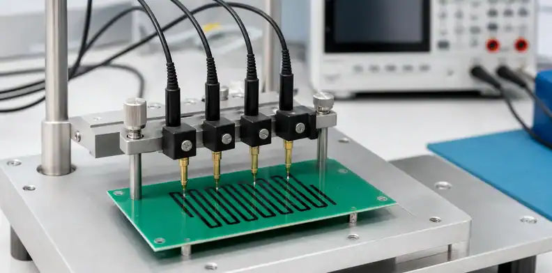
Quick Answer: Carbon ink acceptance should define the printed feature, cured resistance target or permitted range, test method, adhesion or wear requirement, mating condition, and lot record. A pad-layout article cannot answer those production questions because the printed ink film is created, cured, measured, and handled after the copper pattern is already finished.
Carbon ink is often used where a product needs a low-cost contact, a printed resistor, a switch interface, or a protected conductive feature. The technical risk is not just whether black ink appears in the correct place. Film thickness, cure condition, resistance, adhesion, abrasion, contact pressure, and the measuring fixture can all change whether the delivered function matches the released design.
Because handling can damage a cured feature before assembly, apply the same order-stage discipline used in PCB packaging and labeling requirements to the specific carbon contact area.
Table of Contents
- Define the carbon ink function
- Separate resistance from sheet resistance
- Control cure as a product requirement
- Inspect adhesion and wear at the real interface
- Keep the test fixture repeatable
- Decide which defects are cosmetic
- Protect the feature through packing and assembly
- Build a carbon-ink RFQ
- Establish a first-lot acceptance sequence
- Control substitutions and repeat orders
Define the carbon ink function
Carbon ink can be a switch contact, a resistive element, a jumper, a keypad interface, or a feature intended to work against a mating contact. These functions do not carry the same acceptance test. A resistive trace needs an agreed electrical value; a contact needs a usable contact area and wear condition; a printed jumper needs continuity and adhesion. Put the intended function beside the artwork callout.
The carbon-ink pad design article explains the layout interface. This article starts after the design is accepted and asks what a buyer should inspect in the finished, cured print.
Function rule: define what the carbon feature must do before selecting a resistance or visual acceptance test.
The PCB electrical-test requirements article gives a separate view of net-level bare-board testing; it should not be mistaken for an acceptance method for a printed carbon feature. For visible print variation, use PCB cosmetic acceptance criteria only after the functional resistance and contact requirements are defined.
Separate resistance from sheet resistance
Resistance measured between two defined terminals depends on the printed path length, width, thickness, ink formulation, and cure. Sheet resistance is a material-related value expressed for a defined square geometry. The two terms should not be substituted in an RFQ because a supplier can meet one statement while the product still misses the other requirement.
State the terminals, nominal value or permissible band, test state, and whether the figure is a finished-feature resistance or a sheet-resistance control. The test plan should also identify whether measurements are taken on every unit, by sample, or on a designated test coupon.
| Requirement | Drawing or test input | Common ambiguity to remove |
|---|---|---|
| Functional resistance | Terminal points and permissible range | Whether probe contact is part of the value |
| Sheet resistance | Ink system and defined geometry | Whether the number applies to the product path |
| Continuity feature | Maximum resistance and current condition | Whether a visual check is being mistaken for an electrical test |
| Contact pad | Mating configuration and contact zone | Whether wear or repeated actuation is expected |
Measurement call: release carbon ink against the value that represents its actual function, not a number copied from another geometry.
Control cure as a product requirement
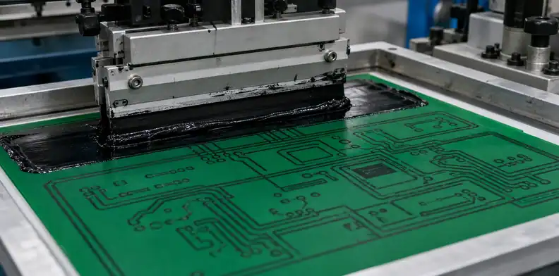
Cure turns a printed wet film into a conductive layer with its intended adhesion and resistance behavior. The fabricator controls the qualified oven route, but the buyer should state the product condition that the cure must support: electrical range, adhesion, thermal exposure, later assembly process, or mating use. A resistance reading taken before the agreed cure state cannot close final acceptance.
Avoid treating time and temperature values from an unrelated ink data sheet as a universal process instruction. Ink systems and substrates differ. Ask whether the proposed ink and cure route are qualified for the board material and whether any subsequent process, such as reflow, cleaning, coating, or adhesive bonding, changes the feature’s expected condition.
A first article may be appropriate when the carbon print is near a connector, keypad, or thermal source. The evidence should identify the same ink feature and cure condition that production will use.
Cure boundary: the supplier owns the qualified cure route; engineering owns the finished electrical and interface requirements.
Inspect adhesion and wear at the real interface
An adhesion test and a wear test answer different questions. Adhesion asks whether the cured film remains bonded to the intended substrate. Wear asks whether a mating action, abrasion, or handling condition changes the surface or electrical behavior. A contact that looks well bonded can still be unsuitable for repeated sliding contact.
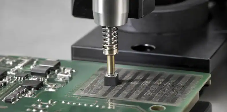
Describe the actual interface: pogo pin, elastomer key, spring contact, enclosure pressure point, human touch, or no mating contact at all. The supplier can then say whether the requested ink system and finished feature suit the use. Do not ask for a generic abrasion claim where the product really needs a controlled contact-resistance or actuation test.
| Use condition | Evidence that fits | Weak substitute |
|---|---|---|
| Static resistive trace | Resistance and adhesion result | Visual color alone |
| Pogo or spring contact | Contact-area inspection and agreed electrical check | A generic cured-film statement |
| Keypad or repeated interface | Defined cycle or wear test where required | One initial resistance reading |
| Protected internal jumper | Continuity and encapsulation compatibility | External abrasion assumption |
Interface check: acceptance evidence should reproduce the product’s contact or handling condition as closely as the project requires.
Keep the test fixture repeatable
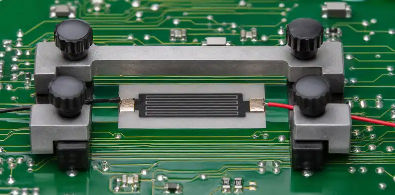
Carbon-ink readings can move when probe location, pressure, terminal definition, or fixture alignment changes. A test value is only useful for supplier comparison when the measurement points and fixture condition are clear. For a multipoint carbon pattern, a purpose-built fixture may be more repeatable than ad hoc hand probing.
The RFQ should specify the controlled terminals and whether a supplied mating part, test jig, or drawing defines the contact. Where every board is tested, the report should retain the product revision and test program identity. Where sampling is used, the sampling plan must match the actual risk rather than simply copying a general electrical-test rule.
Fixture rule: compare carbon values only when the probe points, contact method, and cure state are held constant.
Decide which defects are cosmetic
Color variation, edge roughness, pinholes, smudges, incomplete print, and contamination do not all have the same significance. A small mark outside a functional area may be cosmetic; the same mark inside a mating zone or narrow resistive path may change performance. The drawing should distinguish critical print boundaries from areas where ordinary appearance limits apply.
Ask the supplier to classify a finding by location and function before proposing rework or use-as-is. Reprinting may alter thickness or resistance, while cleaning may damage the contact surface. The disposition needs to state whether the affected feature remains inside the electrical and interface requirement.
For receiving, retain an approved photo only when it defines a real functional visual boundary. A collection of unlinked images does not help a later inspector decide whether a defect matters.
Cosmetic boundary: visual acceptance follows the function of the printed region, not the fact that the ink is black.
Protect the feature through packing and assembly
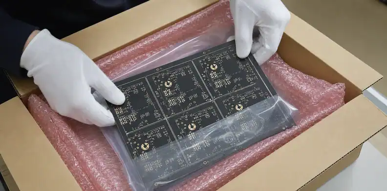
Carbon ink can be damaged after fabrication by abrasive separators, fingerprints, incompatible cleaning, adhesive overlap, soldering heat, or a fixture that touches the print. The manufacturing package should state any handling limits and identify the contact area where ordinary packaging or assembly steps could change the result.
The buyer should also check whether the finished board will be cleaned, conformally coated, potted, or pressed against another part. These downstream operations may be routine for the PCB but incompatible with a particular printed feature. The supplier needs this information before offering an ink or cure recommendation.
On a repeat order, carry the approved ink feature, test method, and packing instruction with the revision. Gerbers alone may not preserve the earlier acceptance decisions. The PCB incoming inspection workflow can assign a practical receiving check to the controlled feature.
Handling rule: a carbon feature remains controlled until its final contact, coating, and packing conditions are known.
Build a carbon-ink RFQ
A carbon-ink quote needs the approved copper artwork, ink-layer artwork, function of each feature, terminal definitions, permitted resistance or sheet-resistance requirement, mating or wear condition, board material, later assembly exposure, and the first-lot record expected by the buyer. Those details turn a printing note into a quote that can be compared and inspected.
Ask the supplier to identify the proposed ink route, cure compatibility, measurement method, sample or lot plan, and any concern about adhesion, contact use, or downstream processing. A supplier response should mark a changed print area or test interpretation before production, not after boards have already been cured.
For a carbon-feature quotation review, send the artwork, target measurement, and intended interface to QueenEMS through the application contact page. The response can distinguish a layout issue from a cure, measurement, wear, or handling condition that needs to be fixed before the order moves into production.
Establish a first-lot acceptance sequence
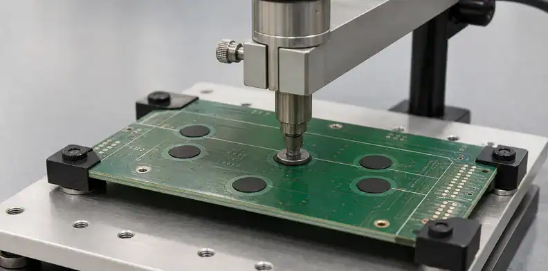
Review the first lot in the order the feature acquires risk: artwork position, cured print condition, electrical value, interface-specific check, and packing or downstream compatibility. This keeps a resistance problem from being treated as a generic printing fault when the cause is a probe fixture, cure state, or wear condition.
| First-lot stage | What to confirm | Release question |
|---|---|---|
| Print location | Carbon matches released artwork | Is the functional zone complete? |
| Cure state | Agreed route is complete | Was testing done after final cure? |
| Electrical check | Terminals and value are defined | Does the result represent product function? |
| Interface check | Wear or contact matches use | Is evidence suitable for the duty? |
| Packing | Surface is protected | Can the board move to assembly safely? |
First-lot rule: verify the feature in the order it is made, measured, and used.
The measurement condition belongs in that sequence as well. State whether resistance is read at printed terminals, a defined connector position, or a functional contact, and record probe geometry or contact force when it materially affects the value. Temperature, cure completion, and any post-print coating can also change a result. This does not require a laboratory-style procedure for every order; it gives the supplier and buyer a repeatable boundary for deciding whether two readings describe the same finished feature.
A broad acceptance range should still be tied to product function. A low-value printed jumper, a resistive element, and a contact surface may each need a different interpretation of the same meter reading. The drawing or acceptance note should state which measurement controls release and which readings are diagnostic only.
This distinction prevents a cosmetic print variation from being judged by the same criterion as a functional contact failure.
Control substitutions and repeat orders
An ink substitution can change resistance, cure behavior, adhesion, appearance, or cleaning compatibility. A revised board artwork can also change the path geometry that produced the accepted value. Ask the supplier to flag a changed ink system, cure route, test method, or handling condition before the next lot uses an old approval as a shortcut.
Supplier comparison should use the finished feature rather than the marketing name of the ink. Two inks described as conductive carbon can have different nominal resistance ranges, recommended substrates, film build, cure response, and contact behavior. The drawing can remain stable while the delivered electrical behavior changes, so a substitution request needs a statement of which product requirement is preserved and which evidence will confirm it.
The same reasoning applies to a revised test method. Moving probe points, changing probe force, or replacing a mating contact can change the measured result even when the print is unchanged. Keep the approved fixture or terminal definition with the product revision. A later buyer can then see whether a new measurement is comparable or starts a new acceptance baseline.
| Change proposed | Why it may alter acceptance | Required decision |
|---|---|---|
| Different carbon ink family | Resistance, adhesion, or cure compatibility can move | Engineering compares product requirement and evidence |
| Modified artwork path | Geometry changes finished resistance | Recalculate or retest the named feature |
| New test fixture | Contact points or force change the reading | Confirm equivalence before comparing results |
| Changed cleaning or coating step | Surface and adhesion may be affected | Check post-process compatibility |
For contact applications, consider whether an initial electrical result is enough. A product that sees repeated contact, pressure, or abrasion may need a limited functional verification after the expected number of use cycles or after the relevant downstream process. The right test is determined by the product duty, not by a universal carbon-ink rule.
Repeat-order check: a substitution is acceptable only after the buyer can compare the same function, same measurement boundary, and same use condition.
Substitution boundary: repeat an accepted carbon result only when the ink, geometry, cure condition, and use interface have not changed materially.
FAQ
Is a carbon ink resistance value the same as sheet resistance?
No. Finished resistance depends on the feature geometry and terminals, while sheet resistance is defined for a specified square geometry and ink condition.
Can visual inspection prove a carbon contact will survive wear?
No. Visual inspection can find surface defects, but a wear or contact question needs an interface-specific check when the product requires it.
Should every carbon feature be tested on every board?
Not always. The test plan should reflect the feature’s function, risk, fixture availability, and the agreed lot-acceptance method.
Can the board be cleaned after carbon printing?
Only after the ink supplier and fabricator confirm compatibility with the cured film and the actual cleaning process. Do not assume a standard PCB wash is harmless.
Sources
Written by the QueenEMS Engineering Team
Upload your files today · Free DFM check before production · Ship worldwide
Get your PCB prototypes in as fast as 24 hours. We handle FR4, Rogers, and hybrid boards up to 40 layers in volume production, with advanced builds subject to engineering review — free prototypes for 2–4 layer FR-4 boards, no minimum order.
Just upload your Gerber + BOM — we source every part, assemble, and inspect (AOI + X‑Ray) so you don't have to chase suppliers. Boards ship in as fast as 24 hours.