
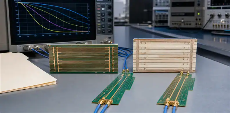
Quick Answer: Treat TUC TU-933 vs TU-953Q as a construction and qualification decision, not a race between two marketing loss tiers. TUC’s current product list identifies ThunderClad 3+ / TU-933+ as a super-low-loss family and ThunderClad 5Q / TU-953Q as an extreme-low-loss family. The buyer should confirm the exact suffix and current TDS, calculate whether the channel needs the higher tier, and approve the glass, resin, copper, pressed thickness, fabrication route, availability, and coupon evidence as one stackup.
TUC TU-933 vs TU-953Q searches often mix current grade names with older TU-933 or TU-933E documents. That is dangerous because a familiar base number does not prove that property values, constructions, or qualification status carry into a current “plus” or “Q” product. The RFQ must begin with exact identity.
This article owns the ThunderClad 3+/5Q procurement boundary. It does not duplicate the existing TUC TU-872 SLK material page or turn every TUC low-loss grade into one table. Use the PCB materials guide when the unresolved question is the broader laminate class.
Table of Contents
- Verify the grade suffix before using any property
- Convert the channel budget into a loss-tier decision
- Compare 3+ and 5Q on a common measurement basis
- Freeze glass, resin, copper, and dielectric geometry
- Check that the fabricator can build the proposed tier
- Qualify the stackup instead of qualifying a trade name
- Control supply changes and lower-tier alternates
- Write a ThunderClad RFQ with no hidden assumptions
Verify the grade suffix before using any property
Identity rule: The approved name must include the current family, exact code and suffix, product form, construction, and data-sheet revision.
TUC’s current product catalog places ThunderClad 3+ / TU-933+ in its super-low-loss group and ThunderClad 5Q / TU-953Q in its extreme-low-loss group. Older public documents for TU-933E describe a related high-speed material, but their values should not be copied onto TU-933+ without a current manufacturer mapping. A suffix may represent a different resin, reinforcement, copper option, property target, or product generation.
Ask the material supplier or fabricator to return the exact commercial identity it will purchase. The answer should show laminate or prepreg, glass construction, resin content, copper foil, thickness, manufacturing source if controlled, and current TDS title/date. Reject a response that shortens the callout to “933,” “953,” or “ThunderClad equivalent.”
Create an identity register before electrical comparison:
| Field | Required response |
|---|---|
| Current product | ThunderClad family and full grade suffix |
| Product form | Copper-clad laminate, core, or prepreg construction |
| Technical record | Current TDS title, revision, and test table |
| Physical construction | Glass, resin content, nominal/pressed thickness, copper |
| Commercial source | Lead time, MOQ, stocking region, approved source |
The register prevents a distributor shorthand or archived PDF from becoming the released design input. It also gives purchasing a precise item to confirm at reorder.
Convert the channel budget into a loss-tier decision
The material tier should close a measured electrical gap. Start with the worst channel, including trace length, connectors, vias, backdrill residuals, copper profile, routing density, operating temperature, and manufacturing tolerance. Determine how much insertion-loss margin is actually attributable to the dielectric.
TU-953Q may provide useful margin when the dielectric loss component is limiting, but an extreme-low-loss designation does not repair a poor via transition, rough foil, excessive stub, or connector discontinuity. TU-933+ may be sufficient when the route is shorter or the architecture has more margin. The economical decision is the lowest tier that meets the validated channel requirement with production tolerance.
For large systems, place connector and drill details in the high-speed backplane PCB RFQ. Then compare TU-933+ and TU-953Q using the same route model. Record frequency points, pass limits, model revision, and the margin remaining after the supplier’s proposed stackup.
Do not use a data-rate label as a substitute for analysis. Encoding, rise time, route length, equalization, topology, and connector loss determine the spectral demand. Two designs advertised at the same speed can require different material tiers.
Run a sensitivity sweep before committing the premium tier. Vary dielectric Df, copper roughness, pressed thickness, trace width, and backdrill residual across realistic production limits. If the channel fails mainly when copper or stub assumptions worsen, moving from TU-933+ to TU-953Q may not address the controlling variable. If dielectric loss remains the dominant term across the tolerance sweep, the extreme-low-loss tier has a clearer technical purpose.
Record the selected corner, not only the nominal result. Production release should be based on the worst supported construction that still meets the system budget. This gives purchasing a measurable reason to reject a lower-tier proposal and gives engineering a reason to accept one when the margin is genuinely sufficient.
Compare 3+ and 5Q on a common measurement basis
Comparison rule: Show method, frequency, specimen, conditioning, and value type beside every Dk or Df number.
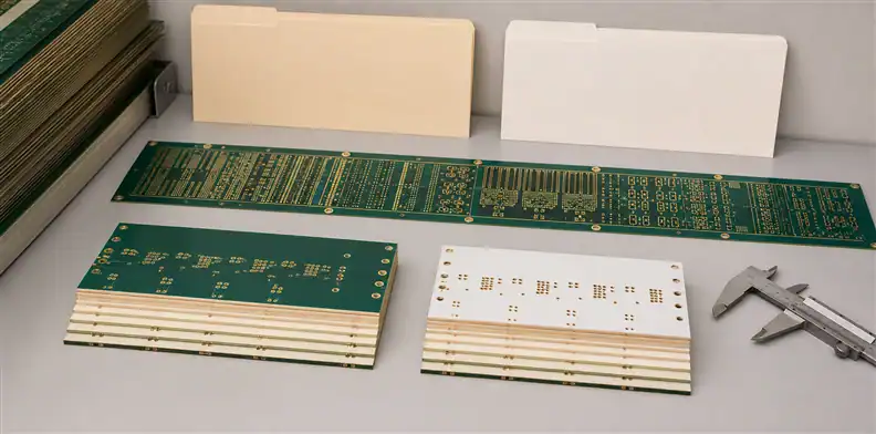
Manufacturer product tables are useful for shortlisting, but values from different document generations or test methods may not be directly comparable. The current TU-933+ and TU-953Q technical records should govern the decision. If the current public TDS is unavailable, the quotation should request it rather than substituting a predecessor’s value.
Normalize the decision in a worksheet:
| Comparison input | Why it belongs in the file |
|---|---|
| Dk and Df source | Preserves test method, frequency, and revision |
| Design Dk | Reproduces impedance and delay calculations |
| Copper model | Prevents resin loss from masking conductor loss |
| Construction | Connects values to glass, resin, and thickness |
| Tolerance or control basis | Separates typical data from acceptance limits |
Do not assume that “5Q” is better in every finished-board metric. A different Dk can change trace width, dielectric height, delay, and coupling. Availability may force a construction that is less convenient for total thickness or impedance. Process familiarity and yield can offset a small theoretical loss advantage.
When the values come from a supplier rather than a public current TDS, keep the response in the controlled project file and state whether it is a typical value, design recommendation, or guaranteed limit. The drawing should not turn a confidential or method-specific number into a universal material specification. Instead, tie it to the named construction, supplier, test context, and approved model revision.
The decision record should state why one tier was selected. Examples include preserving a named insertion-loss margin, holding a target geometry, matching a qualified platform, or avoiding an unneeded material premium. “Latest grade” is not an engineering reason.
Freeze glass, resin, copper, and dielectric geometry
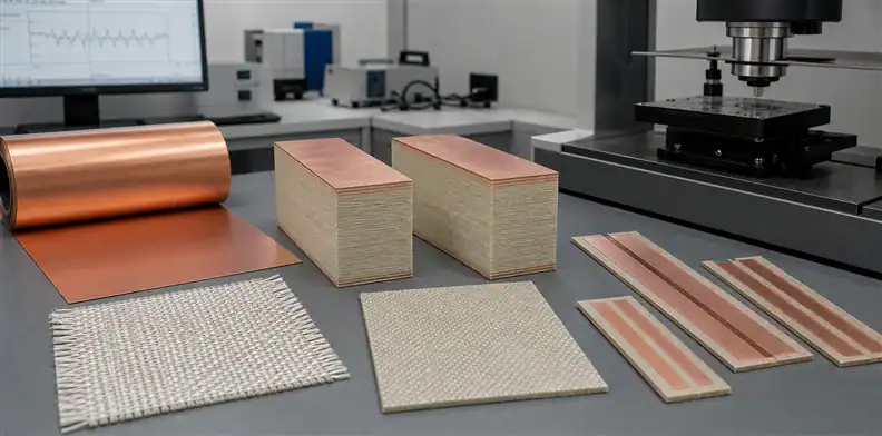
A grade name does not define a transmission line. The returned stackup must identify each core and prepreg construction, glass style, resin content, supplied or pressed dielectric thickness, starting copper, finished copper, and foil profile.
Glass and resin affect effective Dk, skew, resin fill, and pressed thickness. Copper profile affects conductor loss and model correlation. Use the PCB copper foil roughness and HVLP review to specify foil evidence without relying on a vague “low profile” note.
Ask the fabricator whether low-Dk glass or another reinforcement option is part of the proposed construction. Do not infer that an option shown in a family brochure applies to every thickness or stocking region. The quote should identify what will be purchased for this board.
Copper distribution needs an approval boundary. CAM thieving may help lamination and plating, but added copper near high-speed fields can alter impedance, plane behavior, or crosstalk. Require a mark-up for changes inside protected zones.
| Stackup row | Values to freeze |
|---|---|
| Signal copper | Foil designation, starting and finished thickness, profile |
| Plane copper | Foil, weight, splits, copper-density constraints |
| Core | Exact grade, glass/resin construction, dielectric thickness |
| Bonding layer | Exact prepreg, predicted pressed thickness, fill basis |
Check that the fabricator can build the proposed tier
Capability rule: Approve the combination of material, thickness, foil, press route, drilling, and inspection—not a supplier’s general claim that it processes TUC.
Review material storage, layup, press profile, scale compensation, copper preparation, desmear, plating, registration, backdrill, routing, and solder-mask compatibility. High-layer-count boards may require more than one lamination cycle, which makes symmetry, resin flow, dimensional movement, and cumulative thickness more significant.
Ask for experience with the exact or closest construction. A supplier that has used TU-933+ cores may not have production history with the proposed TU-953Q prepreg, ultra-thin dielectric, or foil. The response should distinguish proven process history from a planned engineering trial.
The supplier stackup sign-off should capture any trace-width adjustments, dielectric substitutions, press changes, or thickness compromises. Resolve them before CAM rather than accepting a nominal stackup that cannot be pressed reliably.
Include drill and reliability constraints in the same review. Finished hole, aspect ratio, copper thickness, backdrill residual, thermal cycles, and CAF risk can determine whether an electrically attractive layer count is manufacturable.
Panel design belongs in the capability discussion as well. Coupon placement, edge clearance, tooling, copper balancing, and usable panel size can affect whether the measured coupon represents the board. Ask whether the quotation assumes a standard panel, whether material sheet size restricts rotation, and whether the proposed panel changes cost or registration risk. Those details can make a seemingly cheaper material tier more expensive in delivered boards.
Qualify the stackup instead of qualifying a trade name
Qualification should reproduce the intended board geometry and process. A generic laminate sample cannot prove the insertion loss of the production trace, and one passing impedance coupon cannot prove material identity or via reliability.
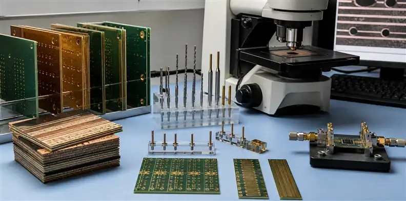
Build a staged evidence plan. The material certificate confirms product and lot. The approved stackup confirms construction. TDR checks impedance. An insertion-loss coupon checks a representative routed structure over the defined frequency range. Microsections verify layer geometry, plating, and hole quality. Reliability tests address thermal cycling, CAF, or other application risks.
Use the PCB impedance test report requirements to make coupon results traceable. For loss data, state the coupon topology, launch, calibration/de-embedding method, frequency points, limit, and file format. Avoid an acceptance line that merely says “SI test passed.”
Set the cadence deliberately. A new grade, supplier, foil, or stackup may need a first-article qualification. Stable production may use lot-level identity and impedance records plus periodic loss audits. A process or material change should reopen only the affected tests, unless customer or regulatory rules require a full requalification.
Define failure handling before the first coupon is measured. The plan should say who reviews an out-of-limit impedance or loss result, whether retest is allowed, how the test setup is checked, and when the panel or lot is placed on hold. A supplier should not average away a failing route or select only the best coupon without an agreed sampling rule.
Correlation samples are useful when the organization changes fabricators or test fixtures. Send or retain a known coupon, preserve its raw measurement file, and compare it under the new setup. Differences caused by launches, calibration, fixture repeatability, or de-embedding can otherwise be blamed on TU-933+ or TU-953Q incorrectly. Record the instrument, calibration state, cables, fixture revision, environmental condition, and analysis software with the result.
For a high-volume product, define trend limits in addition to pass/fail limits. A gradual shift in impedance, insertion loss, pressed thickness, or drill result can reveal process drift while all boards still pass. Trending by material lot and stackup revision lets engineering investigate before margin disappears. It also creates evidence for whether the selected loss tier remains stable enough for future cost optimization.
Control supply changes and lower-tier alternates
Change rule: A lower-cost or available grade remains a proposal until electrical, fabrication, quality, and purchasing owners approve its defined scope.
Request lead time, MOQ, standard constructions, foil availability, and stocking source during quotation. If TU-953Q is not available in the modeled thickness, determine whether a different construction, TU-933+, or another family requires geometry and channel revalidation. Do not let schedule pressure collapse these into one “equivalent material” line.
An alternate package should compare exact material identity, Dk/Df basis, glass/resin construction, copper, thickness, thermal and reliability attributes, process route, and evidence plan. Use PCB material substitution approval to record part numbers, lots, model revision, tests, and whether approval is temporary.
Partial changes count. Replacing only prepreg, foil, or one core may alter the channel. The approved bill of materials should be checked against receiving and traveler records so the production lot can be traced to the decision.
For temporary schedule relief, define an expiration condition. State the approved quantity or lot range, the construction allowed, required first-article evidence, and whether the next order returns to the original grade. Purchasing should not extend a temporary alternate simply because it appears on a previous PO. A permanent change needs a revised baseline and the same review visibility as the original selection.
Write a ThunderClad RFQ with no hidden assumptions
The released package should contain native Gerber or ODB++ data, fabrication drawing, netlist, layer map, proposed stackup, impedance classes, channel-loss requirement, material and foil callouts, drill/backdrill table, coupon drawings, acceptance limits, quantities, panel restrictions, and named approvers.
Require the quote response to list exceptions rather than burying them in pricing notes. It should identify the exact ThunderClad grade per layer, constructions, copper, model values, required geometry changes, lead time, MOQ, source, qualification route, and proposed alternates.
Archive the approved supplier response with the model and PO revision. At repeat order, verify that the suffix, construction, foil, source, and test plan remain unchanged. Define the lot-record package with the pre-shipment PCB quality document requirements once engineering has frozen the baseline.
Ask QueenEMS engineering to review the controlled files when outside fabrication feedback is needed. The quotation can then answer a precise TU-933+ or TU-953Q construction instead of guessing which loss tier the buyer intended.
Purchase decision: Select the tier whose production stackup closes the channel budget with evidence; do not pay for a product label that was never connected to the route model.
FAQ
Are TU-933, TU-933E, and TU-933+ the same material?
Do not treat them as the same without a current TUC cross-reference. Preserve the exact suffix and use the current grade-specific technical record for any numeric design input.
Is TU-953Q always lower loss than TU-933+?
TUC places them in extreme-low-loss and super-low-loss tiers respectively, but finished-channel performance depends on the exact construction, copper, geometry, and test basis. Compare the proposed stackups in one model.
Can a fabricator choose between the two grades during quoting?
The fabricator may propose an alternate, but engineering must approve the resulting model, geometry, process, evidence, cost, and schedule. Purchasing should not authorize an open substitution.
What should be checked at reorder?
Confirm the full suffix, laminate/prepreg constructions, foil, manufacturing source, approved stackup revision, and evidence cadence. Reopen approval if any controlled field changed.
Sources
- Taiwan Union Technology Corporation, current high-speed material product list
- Taiwan Union Technology Corporation, TU-933 product information
Written by the QueenEMS Engineering Team
Upload your files today · Free DFM check before production · Ship worldwide
Get your PCB prototypes in as fast as 24 hours. We handle FR4, Rogers, and hybrid boards up to 40 layers in volume production, with advanced builds subject to engineering review — free prototypes for 2–4 layer FR-4 boards, no minimum order.
Just upload your Gerber + BOM — we source every part, assemble, and inspect (AOI + X‑Ray) so you don't have to chase suppliers. Boards ship in as fast as 24 hours.