
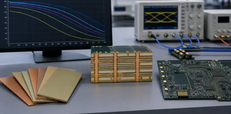
Quick Answer: TUC TU-872 SLK PCB material is a low-loss, modified-epoxy FR-4 system with published Dk 3.8 and Df 0.009 at 10 GHz for 50% resin content. TUC reports Tg values of 220°C by DMA, 200°C by DSC, and 190°C by TMA, so the material offers a practical combination of signal-integrity and lead-free assembly performance—but it still requires construction-specific modeling and a controlled procurement specification.
Key takeaways – TUC classifies TU-872 SLK as a low-loss laminate, not ordinary high-Tg FR-4. – Its published 10 GHz values are Dk 3.8 and Df 0.009 at 50% resin content. – IPC-4101E slash sheets include /29, /99, /101, and /126; TUC lists /126 QPL validation. – “TU-872 SLK or equivalent” needs measurable approval criteria, not just a matching Tg.
TUC TU-872 SLK PCB material fits designs that need lower channel loss than conventional FR-4 but do not automatically justify the cost or fabrication changes of a premium ultra-low-loss system. The difficult part is not finding one attractive Df number. It is deciding whether the published test condition represents your stack-up, whether the required compliance evidence exists, and how tightly an alternate material must be controlled.
For the wider material-selection picture, including laminate properties, process constraints, and substitution risks, see our PCB materials guide.
This guide turns TUC’s current public data into a design and purchasing decision. It also separates verified specifications from assumptions that often enter material comparison tables.
Table of Contents
- What Is TUC TU-872 SLK and Where Does It Fit?
- Which TU-872 SLK Datasheet Values Control Your Design?
- How Do TU-872 LK, SLK, and SLK Sp Differ?
- How Does TU-872 SLK Compare with FR408HR and I-Speed?
- Is TUC TU-872 SLK Halogen-Free?
- When Should You Step Up to Megtron-Class Materials?
- What Does QPL Certification Actually Prove?
- Which High-Speed Applications Fit TU-872 SLK?
- How Should a Fabricator Process TU-872 SLK?
- What Does “TU-872 SLK or Equivalent” Permit?
What Is TUC TU-872 SLK and Where Does It Fit?
TU-872 SLK is a modified-epoxy FR-4 laminate system built with regular woven E-glass. TUC identifies TU-872 SLK as the laminate core and TU-87P SLK as the matching prepreg, and places the family in its Low Loss Laminates category. That positioning matters: it is intended for high-speed, low-loss, and high-frequency multilayer boards rather than as a simple thermal upgrade to standard FR-4.
The material’s useful middle position is architectural, not a universal bitrate label. It can reduce dielectric loss while retaining familiar modified-FR-4 processing, but total insertion loss still depends on trace length, copper profile, glass weave, resin content, geometry, and frequency. A short, well-routed link may not need it; a long backplane channel may need something lower-loss.
TUC lists servers, telecommunications equipment, base stations, storage products, line cards, office routers, backplanes, and high-performance computing among the applications. Those are fit indicators, not proof that every 10, 25, or 56 Gbps channel will pass. Start with the channel budget, then use a PCB material selector to narrow the candidate class before requesting a construction.
For an RFQ, specify both TU-872 SLK and TU-87P SLK, plus the intended copper type, finished thickness, impedance requirement, and assembly profile. That prevents a laminate-only callout from leaving the prepreg system undefined.
Which TU-872 SLK Datasheet Values Control Your Design?
The most useful published values are Dk 3.8 and Df 0.009 at 10 GHz for 50% resin content, together with the thermal and dimensional data that constrain fabrication and assembly. These are material-characterization values, not a finished-board guarantee, so they must be tied to the actual glass style, resin content, copper roughness, and test method used in your model.
| Property | Published value | Why it matters |
|---|---|---|
| Dk at 10 GHz, RC 50% | 3.8 | Starting input for impedance and delay correlation |
| Df at 10 GHz, RC 50% | 0.009 | Indicates dielectric-loss class, not total channel loss |
| Tg by DMA / DSC / TMA | 220 / 200 / 190°C | Shows why Tg numbers must include the method |
| Td by TGA | 340°C | Indicates decomposition onset under the stated test |
| T260 / T288 | 60 / 20 minutes | Supports thermal-exposure review |
| Z-axis expansion, 50–260°C | 2.3% total | Relevant to via and multilayer reliability |
The three Tg values are not contradictory. Dynamic mechanical analysis (DMA), differential scanning calorimetry (DSC), and thermomechanical analysis (TMA) detect the glass transition differently. Writing only “Tg 190°C” discards useful context; writing “dual Tg 170/190°C” does not match TUC’s current public data.
TUC also reports a 340°C decomposition temperature, 60 minutes at T260, 20 minutes at T288, and 2.3% total Z-axis expansion from 50°C to 260°C. These support lead-free process planning, but reliability still depends on moisture control, drill quality, plating, via geometry, reflow count, and peak profile. Ask the fabricator for the construction-specific field or effective Dk used in impedance modeling rather than copying 3.8 into every solver.
How Do TU-872 LK, SLK, and SLK Sp Differ?
Treat TU-872 LK, TU-872 SLK, and TU-872 SLK Sp as separate controlled product names, not as a simple good-better-best ladder inferred from their suffixes. TUC’s current public summaries report the same Dk 3.8 and Df 0.009 at 10 GHz for both LK and SLK, with the same 220/200/190°C Tg set. That does not prove the products are interchangeable; it proves that an older comparison claiming LK is Df 0.014 should not control a new purchase without the exact datasheet revision.
SLK Sp is visibly differentiated in the current data. TUC describes it as using novel woven glass and reports Dk 3.5 and Df 0.008 at 10 GHz for 50% resin content. It also lists IPC-4101E /98 in addition to /29, /99, /101, and /126. Those differences can matter for loss, skew, construction availability, and qualification.
| Family member | Published Dk / Df at 10 GHz | Publicly stated distinction |
|---|---|---|
| TU-872 LK | 3.8 / 0.009 | Separate LK product identity |
| TU-872 SLK | 3.8 / 0.009 | Core TU-872 SLK with TU-87P SLK prepreg |
| TU-872 SLK Sp | 3.5 / 0.008 | Novel woven glass; includes /98 listing |
Before releasing Gerbers, ask for the manufacturer TDS and availability matrix tied to the exact core, prepreg, thickness, glass style, copper, and region. Do not let a distributor or fabricator shorten all three to “872.”
How Does TU-872 SLK Compare with FR408HR and I-Speed?
TU-872 SLK, Isola FR408HR, and I-Speed can enter the same shortlist, but their datasheet numbers are not automatically comparable. Dielectric properties change with frequency, resin content, conditioning, and test method. A smaller Df printed on one sheet does not establish lower loss in your production stack-up unless the measurement basis and construction are aligned.
A useful comparison starts with four questions: Can the fabricator obtain stable core and prepreg constructions? What design Dk do they use for impedance? Which copper profiles are available? Does the modeled insertion loss retain margin after material and process tolerances? The answers are more actionable than a brand-only ranking.
The FR408HR material guide is useful when thermal robustness and hybrid stack-ups dominate. The I-Speed low-loss overview covers another high-speed epoxy option. For each candidate, request the same stack-up geometry, copper assumption, target impedance, frequency range, and channel length, then compare simulated and coupon results on that common basis.
Choose the material that passes the electrical, thermal, compliance, supply, and fabrication gates together. A nominal specification win is irrelevant if the chosen construction is unavailable or the fabricator cannot correlate impedance to it.
Is TUC TU-872 SLK Halogen-Free?
Do not claim TU-872 SLK is halogen-free from the public product page alone. TUC describes it as lead-free-process compatible, and its broader product information discusses RoHS compliance, but RoHS and halogen-free are different requirements. RoHS restricts specified hazardous substances; a halogen-free declaration normally needs limits and evidence for chlorine and bromine.
If the end product has an environmental requirement, request a current material declaration or certificate that names TU-872 SLK, the manufacturing site, applicable limits, revision, and date. Also confirm whether solder mask, legend, bonding materials, and other board constituents fall inside the customer’s declaration scope. A compliant laminate does not make the assembled PCB automatically compliant.
Put the actual requirement on the purchase documentation—for example, the customer’s restricted-substances specification and required evidence—rather than the ambiguous phrase “green material.” If halogen-free construction is mandatory and TU-872 SLK evidence does not meet the requirement, select a grade explicitly documented for it instead of relying on family association.
When Should You Step Up to Megtron-Class Materials?
Step up only when a channel or reliability analysis shows TU-872 SLK cannot maintain the required margin in a buildable stack-up. The decision is driven by total loss, crosstalk, skew, impedance tolerance, thermal exposure, layer count, and fabrication capability—not by a single data-rate threshold.
Begin with the longest and most sensitive channels. Model conductor and dielectric loss with the proposed copper profile, route geometry, vias, connectors, and temperature. Then run tolerance cases for dielectric thickness, line width, Dk, and copper roughness. If the worst-case result is close to the receiver limit, a lower-loss family may provide a cleaner margin than aggressive routing constraints.
For premium alternatives, review the Megtron 4 material guide and Megtron 6 PCB material overview, but compare actual constructions and supplier capability. Hybrid stack-ups can also be valid when only selected layers carry loss-sensitive links, provided resin compatibility, lamination behavior, registration, and reliability are approved.
At this point, one contextual review is useful: send the stack-up, longest channel, interface, insertion-loss budget, copper assumption, and assembly profile through the QueenEMS contact page for a material and DFM assessment. The goal is to identify the lowest-risk buildable option, not automatically the lowest-Df laminate.
What Does QPL Certification Actually Prove?
TUC states that TU-872 SLK has IPC-4101E/126 Validation Services QPL certification. This is meaningful evidence that the qualified product has been evaluated against the applicable slash-sheet framework, but it is not blanket approval for every government, aerospace, or defense program—and it does not qualify the finished PCB.
IPC-4101 covers base materials for rigid and multilayer printed boards. Slash sheets define property sets, while a Qualified Products List (QPL) identifies products qualified through the relevant validation program. Your program may still require an approved manufacturer, named production site, lot traceability, certificates of conformance, test coupons, source inspection, or additional customer specifications.
Use the QPL claim as one item in a traceable compliance chain. Verify the current listing, product name, slash sheet, manufacturing location, and certificate status at the time of purchase. Then flow the applicable requirements to the fabricator and preserve the laminate certificate with the lot record.
This distinction prevents a common sourcing mistake: converting “the laminate is QPL-listed to /126” into “any board made with it is approved for a controlled program.” Qualification scope must be checked at material, fabricator, process, and finished-board levels.
Which High-Speed Applications Fit TU-872 SLK?
TU-872 SLK is a credible candidate for servers, telecom equipment, storage systems, line cards, routers, base-station electronics, backplanes, and high-performance computing—the applications TUC itself lists. Whether it fits a particular design depends on the channel architecture and construction rather than the product category alone.
For server and storage boards, review long differential pairs, connector transitions, via stubs, and dense breakout regions. In telecom and base-station hardware, separate high-speed digital requirements from true RF or microwave requirements; a material suitable for digital backhaul is not automatically the right choice for every antenna or power-amplifier path. The 5G base-station material guide explains this partitioning.
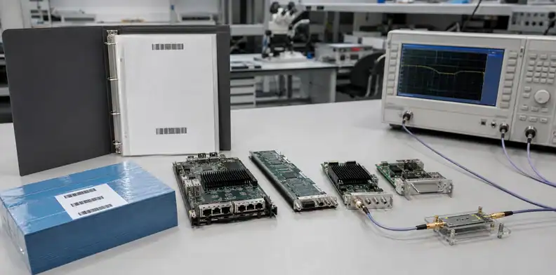
For emerging interfaces, the PCIe Gen6 PCB material guide shows why loss budget, connectors, vias, and copper roughness must be considered as a system. A fabricator should return an impedance table and, where risk warrants, insertion-loss or time-domain reflectometry coupon data tied to the production panel.
Use TU-872 SLK when the modeled channel passes with sensible manufacturing margin and the required construction is qualified. If success depends on ideal copper, zero process variation, or an unavailable glass style, the material choice is not production-ready.
How Should a Fabricator Process TU-872 SLK?
TUC describes TU-872 SLK as compatible with modified FR-4 processes, but the fabricator should still build a material-specific traveler. Receiving control, storage, moisture handling, lamination, drilling, desmear, plating, surface treatment, and final inspection must follow current supplier guidance and the board’s risk profile.
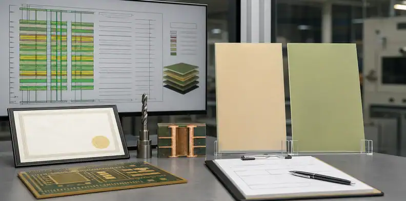
The release package should state the exact core and prepreg names, approved constructions, copper profile, finished thickness, resin-content assumptions, controlled-impedance layers, tolerances, and substitution rule. For a multilayer PCB, include stack-up notes that distinguish nominal datasheet Dk from the fabricator’s design Dk. If the design uses blind or buried vias, align the material decision with the HDI PCB process and its sequential-lamination demands.
Useful preproduction checks include:
- Confirm laminate and prepreg certificates match the purchase order and lot.
- Review pressed thickness and resin-flow assumptions before impedance tuning.
- Use supplier-approved drill and desmear parameters, then inspect representative holes.
- Approve impedance and loss coupons where the channel risk justifies them.
- Record assembly excursions and moisture controls for reliability traceability.
Avoid publishing universal press cycles or drill feeds in the drawing. Equipment, construction, panel size, glass style, and lot behavior affect those values; the qualified fabricator should own and document its process window.
What Does “TU-872 SLK or Equivalent” Permit?
By itself, “TU-872 SLK or equivalent” permits too much interpretation. An alternate can match Tg yet differ in Df, Dk, Z-axis expansion, copper adhesion, moisture behavior, glass styles, copper availability, slash-sheet status, or design-Dk correlation. Equivalence should therefore be a controlled engineering decision, not a purchasing shortcut.
Define the approval boundary in the fabrication drawing or procurement specification. Require the alternate’s manufacturer and product name, matching IPC slash sheet where applicable, comparable method-bound electrical data, thermal and dimensional limits, environmental evidence, and construction availability. Add customer approval before substitution when signal integrity, reliability, or compliance is critical.
The comparison should be construction-specific. Re-run impedance and channel analysis with the candidate’s fabricator-approved design Dk and copper profile; review lamination and drilling compatibility; and decide whether a new coupon, first-article, or reliability test is necessary. “Same or better Df” is insufficient if the test method differs or the stack-up cannot be built consistently.
For a quotation, send the Gerbers or ODB++ package, stack-up, impedance table, interface speeds, longest critical channels, assembly profile, compliance requirements, annual volume, and approved-equivalent policy through QueenEMS quotation support. That package lets engineering quote TU-872 SLK accurately and identify any substitution that needs written approval.
FAQ
Can I use the published Dk 3.8 directly in my field solver?
No. Use 3.8 as a reference point, then obtain the fabricator’s construction-specific design Dk for the selected glass style, resin content, frequency range, and test correlation.
Is TU-872 SLK automatically suitable for 25 Gbps links?
No. Suitability depends on total channel length, geometry, copper roughness, vias, connectors, loss budget, and manufacturing tolerances; verify it by channel modeling and appropriate coupons.
Does lead-free compatibility mean halogen-free?
No. Lead-free process compatibility concerns assembly temperature exposure, while halogen-free status requires separate chemical limits and supporting declarations.
Is TU-872 SLK Sp always a drop-in upgrade?
No. Its published Dk 3.5 and Df 0.008 differ from SLK, and its novel woven glass and construction availability can change impedance, skew, stack-up, and qualification work.
How do I approve an equivalent material safely?
Require a named alternate, comparable method-bound data, the applicable slash sheet, construction availability, compliance evidence, and written engineering approval after stack-up and channel revalidation.
Sources
- TUC TU-872 SLK official product data
- TUC TU-872 LK official product data
- TUC TU-872 SLK Sp official product data
- TUC IPC-4101 slash-sheet and QPL listings
- IPC-4101 specification overview
Written by the QueenEMS Engineering Team
Upload your files today · Free DFM check before production · Ship worldwide
Get your PCB prototypes in as fast as 24 hours. We handle FR4, Rogers, and Flex up to 60 layers — free prototypes for 2–4 layer boards, no minimum order.
Just upload your Gerber + BOM — we source every part, assemble, and inspect (AOI + X‑Ray) so you don't have to chase suppliers. Boards ship in as fast as 24 hours.