
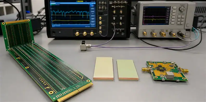
Quick Answer: Choose Meteorwave 8000 when the dominant requirement is extremely low-loss high-speed digital routing, and evaluate Meteorwave 8300 when controlled Dk near 3.0 and RF/microwave circuit behavior drive the design. Do not rank the two by Dk alone. A defensible Meteorwave 8000 vs 8300 decision must compare the current laminate/prepreg construction, Dk and Df test basis, copper foil, glass style, thickness availability, fabrication route, and the coupon evidence that represents the intended channel or RF structure.
Meteorwave 8000 vs 8300 looks like a simple product-number comparison, but the two AGC materials occupy different design conversations. Meteorwave 8000 is positioned as an extremely low-loss high-speed laminate and prepreg. Meteorwave 8300 is based on that platform and tailored around controlled Dk for RF and microwave use. Substituting one for the other can change trace geometry, phase length, loss prediction, and the manufacturing construction.
This comparison helps a buyer turn the electrical use case into a quoteable material decision. Broader material-family screening belongs in the PCB materials guide; the sections below focus on the evidence that separates these two Meteorwave choices.
Table of Contents
- Start with the circuit behavior, not the product number
- Read the 8000 and 8300 data in their intended context
- Reconcile test methods before comparing dielectric values
- Rebuild geometry and phase length for the chosen material
- Expose copper, glass, and resin variables in the quote
- Qualify the actual fabrication route and test vehicle
- Evaluate substitutions without erasing the use case
- Make the quotation response prove the decision
- Preserve separate digital and RF production baselines
Start with the circuit behavior, not the product number
Routing decision: Classify the board by the structures that consume margin: long digital channels, controlled-phase RF lines, antennas, filters, mixed-signal regions, or a hybrid of those needs.
AGC describes Meteorwave 8000 as an extremely low-loss material for high-speed digital applications such as telecommunications, storage, and backplanes. Its current product page rounds Dk to 3.3, while the June 2026 AGC Solutions Guide lists Dk 3.28 and Df 0.0016 at 10 GHz. Meteorwave 8300 is described as a controlled-Dk material tailored for RF and microwave applications; the same current guide lists Dk 3.0 and Df 0.0025 at 10 GHz. These are typical guide values rather than finished-board guarantees, so the project must preserve the source revision and the design value used in simulation.
For a digital switch card, the central problem may be insertion loss over a long differential path with connectors and vias. For an antenna feed or filter, phase consistency, geometry, effective Dk, dimensional stability, and frequency-specific loss can dominate. A mixed board may need both behaviors on different layers. The buyer should identify the critical structures before asking which Meteorwave grade is “best.”
Write the requirement in measurable terms: target impedance, frequency band, route length, insertion-loss limit, phase or delay tolerance, temperature range, copper model, and required margin. A material can be excellent for one of those conditions without being the economic or technical choice for the other.
When the board contains a complex long channel, use the high-speed backplane PCB RFQ for connector, backdrill, press-fit, and system-level fields. Here, keep the decision centered on which Meteorwave material system supports the modeled structure.
Read the 8000 and 8300 data in their intended context
Meteorwave 8000 and 8300 should be treated as two controlled systems, not as one resin with two interchangeable labels. Confirm the current technical data sheet, laminate and prepreg availability, thicknesses, glass constructions, copper options, and regional supply before freezing a stackup.
The word “controlled” in controlled Dk matters in RF design, where phase length and resonant geometry can be sensitive to dielectric variation. It does not mean every finished circuit will measure exactly the summary Dk. Effective Dk depends on the field distribution, copper thickness, surface treatment, dielectric thickness, glass/resin structure, and the chosen model.
Likewise, the very low published Df of Meteorwave 8000 is useful to a digital loss budget only when the board construction preserves that advantage. Rough copper, an unsuitable weave assumption, long via stubs, or an unmodeled connector can outweigh a small resin-loss difference.
Build a product-identity block for each candidate:
| Identity field | Meteorwave 8000 response | Meteorwave 8300 response |
|---|---|---|
| Current product form | Laminate/prepreg construction | Laminate/prepreg construction |
| Intended circuit role | Digital channel or mixed use | RF/microwave structure or mixed use |
| Dk/Df source | TDS revision and method | TDS revision and method |
| Glass and resin construction | Supplier-proposed stackup | Supplier-proposed stackup |
| Copper foil | Named foil and profile | Named foil and profile |
| Availability | Thickness, lead time, MOQ | Thickness, lead time, MOQ |
This prevents a distributor description or an old data sheet from becoming the de facto design record.
Reconcile test methods before comparing dielectric values
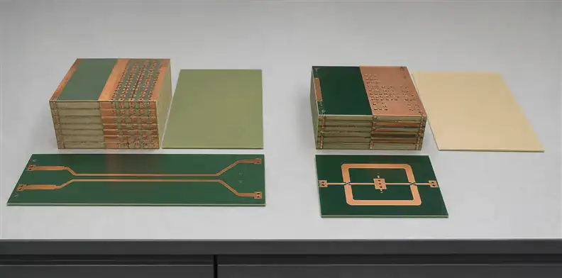
Data rule: Compare values only after the frequency, method, specimen, axis, conditioning, and value type are visible beside them.
Dk can be reported as a typical material value, a process specification value, or a design value correlated to a circuit. Df can move with frequency and test method. A summary guide may be suitable for shortlisting, while the current TDS and supplier-supported stackup values are needed for design release. Never subtract two numbers from unrelated methods and call the result a guaranteed loss advantage.
Request a normalized comparison table from the engineering owner or fabricator. It should state the selected Dk and Df, where they came from, the frequency, and whether a tolerance or lot-control limit exists. If the value will drive a field solver, record the solver model and any anisotropy assumptions.
The same caution applies to “controlled Dk.” Ask what production or material control supports the claim and how it maps to the finished circuit acceptance method. A material certificate may report resin or laminate properties, while the finished board is checked through impedance, phase, resonator, or insertion-loss structures. Those are related but not interchangeable observations.
For controlled-impedance routes, align the value table with the controlled impedance PCB manufacturing process. The fabricator should return a stackup using values it can support, while the buyer approves any resulting change in trace geometry.
Avoid a common procurement shortcut: specifying both a fixed trace width and an impedance target without giving a rule for conflict. If the pressed dielectric or copper differs from the model, the fabricator may need an approved width change. The RFQ should state who can authorize it.
Rebuild geometry and phase length for the chosen material
Changing from Meteorwave 8000 to 8300 can alter more than the material line in a bill of materials. A lower nominal Dk may require wider traces or different dielectric height to preserve impedance, and it changes propagation delay and electrical length. In an RF filter, coupler, antenna feed, or phased network, that can move the response even if the impedance remains correct.
Rerun the relevant structures using the exact proposed construction. For digital channels, check insertion loss, return loss, crosstalk, skew, via fields, and connector launches. For RF structures, check impedance, phase, resonant dimensions, conductor and dielectric loss, launch behavior, radiation, and temperature sensitivity. Mixed boards should evaluate transitions between material regions and reference planes.
Do not let a supplier’s impedance adjustment become an undocumented RF redesign. A small width or spacing change can be acceptable, but the RF owner must see the updated geometry and model. Define protected features where CAM must request approval rather than applying routine compensation.
Use coupons that resemble the critical physics. A generic impedance line may not represent a narrow coupled structure, grounded coplanar waveguide, filter resonator, or long differential channel. The coupon plan should state which dimensions and process steps must match production.
If the design uses multiple material families, the high-frequency hybrid PCB stackup review can own the interface, bonding, and mixed-CTE questions. This Meteorwave comparison should still identify which layers use 8000 or 8300 and why.
Expose copper, glass, and resin variables in the quote
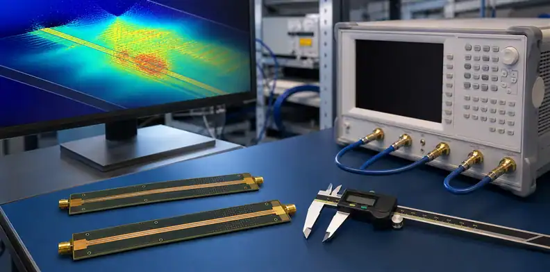
Construction check: A material name without foil, glass, resin, and pressed-thickness information is not a complete high-frequency stackup.
Conductor loss grows in significance as frequency rises. Copper profile and adhesion treatment influence current path length, effective impedance, and model correlation. Require a named foil option and the roughness information used by the model. If different foils are proposed for inner and outer layers, list them separately.
The PCB copper roughness and HVLP RFQ provides the terminology and evidence fields for that decision. In the Meteorwave stackup, map the chosen foil to every critical signal layer rather than putting one ambiguous note at the bottom of the drawing.
Glass style and resin content affect effective Dk, skew, thickness, and resin fill. Ask for the production construction that corresponds to the quoted thickness. For sensitive differential routes, compare the trace pitch and orientation with the weave. For RF structures, evaluate whether local resin/glass variation changes phase or resonance enough to require routing or material controls.
Copper density also affects lamination. Sparse and dense regions can press differently, especially around planes, voids, or large RF clearances. If CAM adds copper balancing, the added pattern must respect fields, plane capacitance, isolation, and RF behavior. State where approval is mandatory.
Separate nominal laminate thickness from pressed prepreg thickness as its own release check. The RFQ should show tolerances or expected ranges and identify which dimensions the impedance or phase model uses. This gives the supplier a chance to propose a buildable construction before artwork is released.
| Construction variable | Returned evidence |
|---|---|
| Copper foil | Commercial foil designation and roughness basis |
| Glass and resin | Construction code, glass style, and resin content |
| Dielectric height | Predicted pressed thickness and tolerance |
| Copper distribution | CAM balancing proposal and approval boundary |
Qualify the actual fabrication route and test vehicle
Fabrication capability is construction-specific. A supplier may have experience with one Meteorwave product, thickness, or foil and no qualified history with the exact combination in the quote. Ask for relevant process experience without treating a vague statement such as “we build low-loss boards” as evidence.
The review should cover material storage, layup, press profile, resin fill, dimensional compensation, drilling and desmear compatibility, copper preparation, plating, surface finish, routing, and any sequential lamination. If the board is hybrid, include bond interfaces and movement through each press cycle.
Define first-article evidence around the design risk:
- stackup and finished-thickness measurements;
- impedance results by relevant layer pair;
- insertion-loss or RF coupon data with frequency and de-embedding details;
- microsections for holes and critical interfaces;
- registration and dimensional results;
- material lot and traveler traceability;
- deviations and approved rework.
The PCB microsection report requirements can support hole and layer evidence, but it cannot prove RF loss by itself. Use each test for the feature it can actually observe.
Establish whether the evidence is required for qualification only, every production lot, periodic audit, or after a material/process change. That distinction keeps the plan economical while preserving control where the design is sensitive.
| Evidence timing | Suitable use |
|---|---|
| First article | Prove a new material, stackup, foil, or supplier route |
| Every lot | Control high-risk identity, impedance, or shipment acceptance |
| Periodic audit | Monitor a stable process without repeating a full qualification |
| After change | Reopen only the evidence affected by the approved change |
Evaluate substitutions without erasing the use case
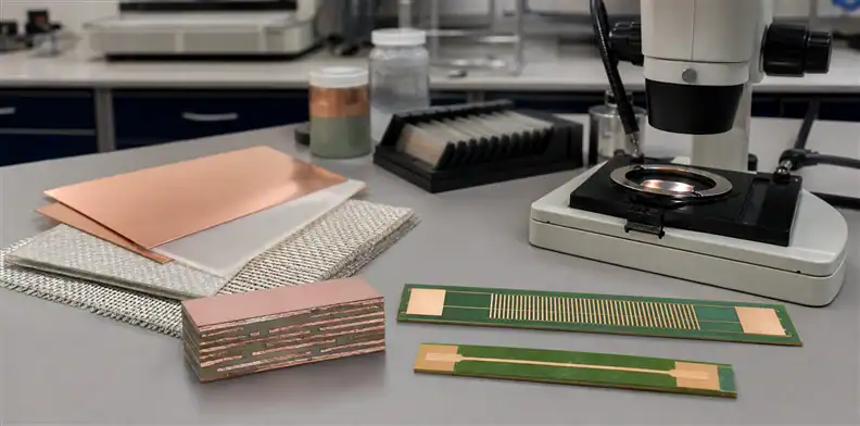
Substitution rule: The proposed replacement must be evaluated against the original circuit function, not against a generic “low-loss” label.
If Meteorwave 8000 is unavailable, a substitute for a long digital channel should be compared on the modeled insertion-loss budget, supported constructions, copper, skew risk, via reliability, and fabrication capability. If Meteorwave 8300 is replaced in an RF structure, phase, Dk control, geometry, TCDk where relevant, loss, and dimensional stability may carry more weight.
Request the current data sheet, exact grade, manufacturing source, available constructions, copper options, lead time, and reason for the proposal. Then classify the change: purchasing source only, construction change within a family, material-family change, or electrical redesign. Each class needs a different approval depth.
The PCB material substitution approval process should identify the affected part, stackup revision, approved lots, model changes, test evidence, and customer notification. Never use “equivalent” as the approval record.
Also control partial substitutions. A supplier might keep the named core but replace the prepreg, or use a different foil on one side. Those changes can alter the result even when the final quotation still mentions Meteorwave. Compare the complete layer construction line by line.
Make the quotation response prove the decision
A quote-ready package contains native fabrication data, drawing, layer map, proposed stackup, impedance table, critical RF geometry, material callout, copper requirements, test-coupon definition, quantities, panel constraints, acceptance limits, and approval contacts. The supplier response should return a marked stackup and a concise list of exceptions.
Ask the response to state:
- whether Meteorwave 8000 or 8300 is quoted and for which layers;
- laminate and prepreg constructions, glass styles, pressed thicknesses, and tolerances;
- foil type and roughness basis;
- Dk/Df values used for impedance, phase, and loss prediction;
- required geometry adjustments;
- material availability, lead time, MOQ, and approved manufacturing source;
- qualification and routine evidence;
- every proposed alternate or process exception.
| Quote response | Approval owner |
|---|---|
| Material identity and availability | Purchasing and component/material engineering |
| Geometry and predicted electrical change | Signal-integrity or RF engineering |
| Press, drill, plating, and inspection route | Fabrication engineering and quality |
| Alternate, deviation, or source change | Named change-control authority |
Preserve the approved response with the model and purchase revision. At reorder, verify that material identity, construction, manufacturing source, and test plan have not drifted. The supplier stackup sign-off becomes the shared baseline rather than an email attachment that cannot be traced.
Send a complete package through the QueenEMS contact page when fabrication review is needed. QueenEMS can then answer the quote against the named construction instead of inferring whether “Meteorwave” means a digital or RF material decision.
Buyer call: Use 8000 for a digital-loss problem and 8300 for a controlled-Dk RF problem only after the proposed construction reproduces the required channel or circuit behavior.
Preserve separate digital and RF production baselines
Baseline rule: Keep a grade-specific construction and evidence history for each circuit role, even when both materials share one purchasing family.
An organization that uses both materials should not let one generic “Meteorwave” specification govern them. Create a baseline for each released construction, including approved layers, laminate/prepreg rows, foil, model values, critical geometry, supplier source, coupon design, and evidence cadence. Link the baseline to the part numbers and drawing revisions where it applies.
Trend production data by use case. For 8000 digital channels, monitor impedance, insertion loss, backdrill, and construction changes that consume equalization margin. For 8300 RF circuits, monitor dimensions, phase or resonant response, Dk correlation, and temperature-sensitive behavior. The data should answer whether the production process remains centered on the original reason for selecting the material.
When a common purchasing item is unavoidable, require the PO and supplier acknowledgement to reference the correct controlled stackup. Receiving should verify the exact grade and construction rather than accepting the family name. This small administrative distinction prevents a stocking decision from turning into an undocumented electrical substitution.
FAQ
Is Meteorwave 8300 always better because its Dk is lower?
No. A lower Dk changes geometry and electrical length, while the application may prioritize dielectric loss, controlled phase, density, thickness, or fabrication availability. Evaluate the complete structure and test basis.
Can Meteorwave 8000 be used for RF circuits?
A material can support more than one application, but suitability depends on the RF structure, Dk control, loss, thickness, copper, phase tolerance, and validated fabrication route. Do not infer approval from the digital product positioning alone.
Should the quote use the AGC solutions guide or the product TDS?
Use the guide for shortlisting and the current product-specific TDS plus supplier construction for release. Record the revision and measurement context for every numeric value used by the model.
What is the minimum useful first-article evidence?
At minimum, require material identity and lot traceability, the approved built stackup, relevant dimensional and impedance results, and the RF or loss coupon evidence defined by the design risk. Add microsections and reliability tests where the construction requires them.
Sources
- AGC Multi Material, Meteorwave 8000
- AGC Multi Material, Meteorwave 8300
Written by the QueenEMS Engineering Team
Upload your files today · Free DFM check before production · Ship worldwide
Get your PCB prototypes in as fast as 24 hours. We handle FR4, Rogers, and hybrid boards up to 40 layers in volume production, with advanced builds subject to engineering review — free prototypes for 2–4 layer FR-4 boards, no minimum order.
Just upload your Gerber + BOM — we source every part, assemble, and inspect (AOI + X‑Ray) so you don't have to chase suppliers. Boards ship in as fast as 24 hours.