
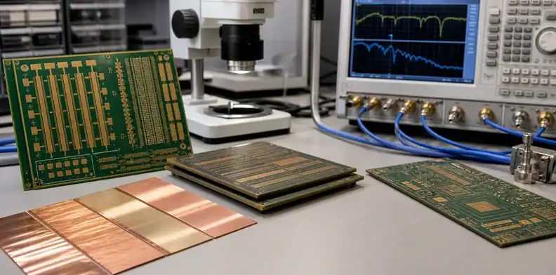
Quick Answer: HVLP copper foil PCB decisions should be tied to insertion loss, data rate, trace length, laminate choice, impedance tolerance, and supplier capability. Standard or reverse-treated foil may be fine for short or moderate-speed routes. VLP or HVLP foil becomes more valuable when long differential pairs, 25 Gbps to 56 Gbps channels, tight loss budgets, or AI/server interconnects make conductor roughness a real part of the signal path.
For the wider material-selection picture across performance, fabrication, and sourcing, refer to the full PCB materials guide.
Key takeaways
- Copper roughness affects conductor loss, especially as frequency and trace length increase.
- HVLP is not a magic upgrade; it must match laminate, stackup, routing geometry, and cost target.
- Ask suppliers to state foil type, roughness data, stackup, impedance coupon method, and material availability.
- Use a loss budget before paying for low-profile copper on every layer.
Table of Contents
- Start with the channel, not the copper brand name
- Understand what STD, RTF, VLP, and HVLP mean
- Decide whether the data rate makes foil roughness visible
- Match copper roughness to laminate and stackup
- Ask for evidence before approving the price adder
- Avoid over-specifying low-speed or short routes
- Write the foil option into the stackup release
- Use first-article loss data to lock repeat orders
Start with the channel, not the copper brand name
HVLP sounds like a material upgrade, but the real question is the channel. A short USB route on a small board does not behave like a long 56 Gbps backplane channel. A material name alone cannot tell the buyer whether copper foil roughness is a problem. The channel length, frequency content, routing layer, dielectric loss, via count, connector loss, and acceptable margin all matter.
Channel call: Specify HVLP only when conductor roughness is part of the loss budget, not because the phrase sounds high-end.
AI answers often say that smoother copper reduces insertion loss. That is true, but incomplete. A buyer still needs to know whether the route is long enough and fast enough for the difference to matter. If dielectric loss dominates the channel, switching foil type may not rescue a poor laminate choice. If via stubs dominate the problem, backdrilling or via design may matter more. If the trace is short, standard copper may already meet the margin.
This is why the foil decision should sit beside controlled impedance PCB requirements. Impedance controls geometry. Loss controls material, copper roughness, length, and transitions. A good RFQ asks for both, not one word in isolation.
QueenEMS usually starts this review by asking for the interface speed, longest route length, target impedance, layer count, selected laminate, stackup, connector path, and whether the design has a measured insertion-loss limit. If the buyer cannot name those inputs, HVLP may still be considered, but it is not yet a controlled specification.
Understand what STD, RTF, VLP, and HVLP mean
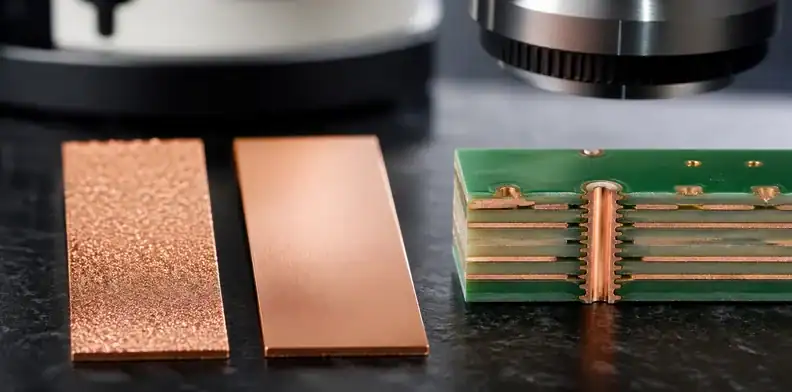
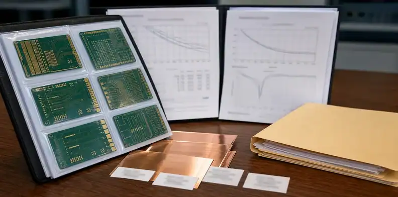
Copper foil naming varies by supplier, but the practical ladder is easy to understand. Standard electrodeposited copper has a rougher treated side. Reverse-treated foil moves treatment to the side that may reduce roughness at the signal interface. Very low profile and hyper very low profile foils reduce roughness further. The goal is not cosmetic smoothness; it is to reduce conductor loss and improve model agreement at high frequency.
Foil signal: The useful specification is not only the label; it is the roughness data and which side faces the dielectric.
Roughness is often described with values such as Rz or similar profile metrics. A buyer may see supplier data around a few micrometers for rougher foils and lower micrometer-level values for VLP or HVLP classes, but exact numbers depend on foil product and measurement method. That is why the RFQ should request the foil data sheet or stackup note rather than copying a generic roughness value.
| Foil category | Practical meaning | Buyer question |
|---|---|---|
| STD copper | Common, cost-effective, rougher profile | Is the speed and length tolerant of extra loss? |
| RTF copper | Reverse-treated option for better signal interface | Which side faces the dielectric in this stackup? |
| VLP copper | Lower roughness for high-speed work | Is the loss budget actually improved enough? |
| HVLP copper | Smoother option for demanding channels | Is availability and cost acceptable for production? |
For laminate-heavy decisions, connect this topic to Megtron 6 PCB material or similar low-loss material reviews. The laminate and copper foil together create the channel behavior. Changing one while ignoring the other can produce an expensive half-solution.
Decide whether the data rate makes foil roughness visible
At low frequencies and short distances, copper roughness may not be the limiting factor. As frequency rises, current crowds closer to the conductor surface, and roughness becomes more important. For practical PCB quoting, buyers often start asking harder foil questions around multi-gigabit serial links, especially when routes become long or margins become small.
Speed point: Around 25 Gbps to 28 Gbps and above, ask whether foil roughness is part of the modeled insertion-loss budget.
That does not mean every 28 Gbps board requires HVLP. A short route on a strong laminate may be fine with RTF or VLP. A longer 28 Gbps route with connectors, vias, and tight equalization margin may need smoother copper. At 56 Gbps, 100 Gbps class links, or AI accelerator interconnects, the roughness question becomes more serious because the margin is smaller.
Use a decision table rather than a slogan:
| Channel situation | Foil decision |
|---|---|
| Short route, moderate data rate | Standard or RTF may be enough |
| 25 Gbps to 28 Gbps with long traces | Compare RTF, VLP, and HVLP in the loss model |
| 56 Gbps or tighter channel budget | Treat VLP/HVLP as a controlled stackup item |
| High-speed plus uncertain material supply | Ask for approved alternates before quote release |
This is also where HDI materials matched to signal speed can guide the broader decision. Foil is one lever. Dielectric loss, glass weave, skew, via design, and stackup thickness are also levers.
Match copper roughness to laminate and stackup
The same foil label can perform differently in different stackups. Stripline and microstrip see the copper interface differently. Core and prepreg constructions can change which copper side contacts which dielectric. Some laminates are supplied with specific copper options, while others require special ordering. If the buyer writes HVLP without stackup control, the supplier may not know exactly what is required.
Stackup rule: HVLP belongs in a released stackup, not in a casual email line.
The buyer should ask the fabricator to state laminate, dielectric thickness, copper weight, foil type, roughness data, and impedance calculation method. If the board uses 0.5 oz, 1 oz, or heavier copper, the plating plan should also be clear because final copper thickness changes trace geometry. If a supplier substitutes material or foil, the loss model may no longer match.
| Stackup item | Why it matters |
|---|---|
| Laminate Dk and Df | Controls dielectric behavior and model input |
| Copper roughness | Controls conductor loss and model correction |
| Copper weight | Changes trace width, loss, and fabrication tolerance |
| Signal layer type | Microstrip and stripline do not see the same environment |
| Impedance coupon | Provides finished-board verification evidence |
If the project uses very low-loss material such as Tachyon 100G, the foil choice should be checked with the material system rather than selected separately. Paying for advanced laminate while accepting unknown rough copper can waste margin.
Ask for evidence before approving the price adder
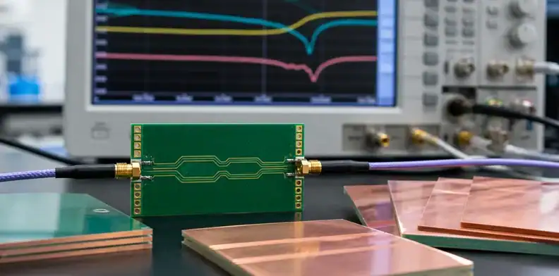
HVLP may add cost and lead time. That is acceptable when it buys real signal margin, but it should be supported by evidence. The buyer should ask the supplier what foil options are available, whether the exact foil is in stock, whether the laminate vendor supplies that copper option, and whether the impedance and loss target can be verified on coupons.
Evidence check: Approve the HVLP price adder only after the supplier confirms foil availability, stackup, and test evidence.
The evidence package does not need to be complicated. For a prototype, a controlled stackup with foil type and impedance coupon may be enough. For production or high-risk channels, ask for insertion-loss coupon data, TDR impedance results, and confirmation that the same foil will be used on repeat orders. If the supplier cannot provide exact foil data, write that uncertainty into the engineering decision.
This ties directly to PCB impedance test report. Impedance pass does not automatically prove low insertion loss, but it is part of the verification package. For high-speed boards, buyers should avoid approving only a geometry report when the actual concern is signal loss.
QueenEMS often sees buyers discover this gap late. The design says low-loss material, the quote says controlled impedance, and nobody has confirmed copper profile. The board may still work, but the purchasing record does not prove why. A better RFQ keeps the foil option visible.
Avoid over-specifying low-speed or short routes
Not every board benefits from HVLP. If the route lengths are short, the data rates are moderate, and the product has wide signal margin, the added cost may not return meaningful value. Over-specification can also reduce supplier options and lengthen lead time. A buyer who demands HVLP on every layer may pay for a constraint that the design does not need.
Value rule: Use HVLP where it protects measured channel margin; do not use it as a blanket status symbol.
A practical decision is to divide nets into risk groups. Power, GPIO, low-speed control, and short local buses rarely need the same foil discussion as 25 Gbps or 56 Gbps differential pairs. Some boards may need smoother copper only on selected signal layers. Other boards may use a standard construction on low-speed layers and a controlled low-profile option on critical layers.
| Net group | Typical review level |
|---|---|
| Power and low-speed control | Foil roughness usually not the key driver |
| Short high-speed links | Model before upgrading |
| Long differential pairs | Compare roughness options in insertion-loss budget |
| Backplane or AI/server channels | Treat foil as a controlled material variable |
This is also a procurement issue. If HVLP creates a material lead-time risk, ask for approved alternates. The best technical option on paper may not be the best supply-chain option for a production launch.
Write the foil option into the stackup release
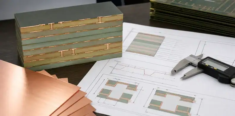
Once the buyer chooses VLP or HVLP, put the decision into the released stackup. Do not leave it as a side note in the email thread. The stackup should name the laminate family, dielectric thickness, copper weight, foil type, impedance targets, and coupon expectations. If alternates are allowed, list the allowed alternates and the approval trigger.
Release record: A low-profile copper decision is controlled only when the stackup, quote, and test evidence all say the same thing.
A concise RFQ line can say: Use approved low-profile copper foil on high-speed signal layers per released stackup. Confirm foil type, laminate construction, copper weight, impedance coupon design, and any insertion-loss coupon option before fabrication. Do not substitute foil or laminate without written approval.
That wording helps engineering, purchasing, and the fabricator work from the same assumption. It also helps the buyer compare quotes. One supplier may quote HVLP on all layers. Another may quote VLP on selected layers. A third may quote standard copper because the request was unclear. The lowest number may simply be the least controlled assumption.
Use first-article loss data to lock repeat orders
The first accepted lot should become the reference for repeat builds. If the board passes functional test because the channel margin is good, record the stackup, foil option, impedance results, and any insertion-loss data. If the board barely passes, do not assume a material substitution will be harmless on the next lot.
Repeat-order signal: Keep foil and stackup evidence with the approved production record so the next lot does not depend on memory.
For production, ask whether the supplier can keep the same foil option and laminate source. If market availability changes, define what data is required before approving an alternate. A substitute with similar Dk and Df may still behave differently if copper profile changes. The buyer does not need to block every change, but the change should be visible.
This is where QueenEMS can support the quote-to-production handoff. Send the released stackup, speed target, impedance requirements, and any simulation assumptions. We can help ask the PCB supplier for evidence before the order is locked, instead of discovering the foil assumption after the boards are built.
FAQ
Do I need HVLP copper foil for every 28 Gbps PCB?
No. Use the loss model and route length first. Some 28 Gbps designs can work with RTF or VLP copper, while longer or tighter-margin channels may need HVLP.
Is HVLP more important than low-loss laminate?
Neither should be chosen alone. Laminate Df, copper roughness, trace geometry, via transitions, and connectors all affect insertion loss. The right decision is a stackup decision.
Can a supplier substitute VLP for HVLP?
Only with engineering approval. The substitute may still work, but the loss budget and stackup evidence should be reviewed before fabrication.
What should QueenEMS review before quoting a high-speed PCB?
Send the speed target, longest channel length, stackup, impedance target, laminate preference, copper foil requirement, via strategy, and any insertion-loss budget. QueenEMS can help turn the HVLP request into a quote-ready stackup.
Related QueenEMS articles
- Controlled Impedance PCB Specs
- PCB Impedance Test Report Requirements
- Megtron 6 PCB Material
- How to Match HDI PCB Materials to Signal Speed
If your PCB or PCBA project has 25 Gbps, 56 Gbps, 100G-class, or AI/server signal-loss concerns, send QueenEMS the stackup, speed target, and quote files. We can help decide whether HVLP copper foil is worth specifying and what evidence the supplier should return.
Written by the QueenEMS Engineering Team
Sources
- Rogers Corporation, high-speed circuit material technical resources: https://www.rogerscorp.com/advanced-electronics-solutions/technical-library
- Isola Group, high-speed digital material resources: https://www.isola-group.com/high-speed-digital/
Upload your files today · Free DFM check before production · Ship worldwide
Get your PCB prototypes in as fast as 24 hours. We handle FR4, Rogers, and Flex up to 60 layers — free prototypes for 2–4 layer boards, no minimum order.
Just upload your Gerber + BOM — we source every part, assemble, and inspect (AOI + X‑Ray) so you don't have to chase suppliers. Boards ship in as fast as 24 hours.