
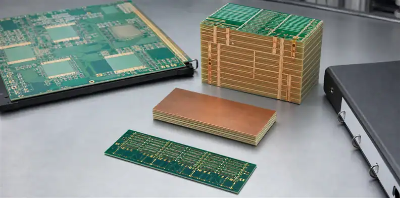
Quick Answer: A Nelco N4000-13 EP SI PCB material order should preserve the exact qualified laminate/prepreg construction, copper, glass, pressed thickness, supplier stackup, and inspection evidence. AGC currently lists N4000-13 EP SI as a modified-epoxy high-speed material with Dk 3.2 and Df 0.008 on its product page, but those summary values do not authorize a replacement or geometry change. For a sustaining product, confirm the current AGC identity, reconcile legacy drawing notes, and treat every source or construction change as a controlled requalification decision.
Nelco N4000-13 EP SI appears frequently on older backplane, network, storage, and telecom drawings. Engineers may call it a legacy material because the platform has a long field history, yet AGC still maintains a current product page. That combination creates a special risk: teams assume either that nothing can change, or that any modern low-loss laminate is automatically superior.
This article addresses sustaining production, exact identity, and requalification. It is not a generic high-Tg FR-4 comparison. For new-material screening, start with the PCB materials guide; for this material, the question is how to preserve an approved design or change it deliberately.
Table of Contents
- Confirm the current AGC identity behind the Nelco note
- Interpret EP and SI without inventing specifications
- Recover the construction that was actually qualified
- Preserve impedance and loss assumptions through reorders
- Connect thermal and CAF claims to acceptance evidence
- Decide when a replacement requires requalification
- Control sustaining lots, records, and deviations
- Issue a reorder package that exposes every change
- Set an exit strategy for an aging qualified platform
Confirm the current AGC identity behind the Nelco note
Identity decision: Keep the historical Nelco name for traceability, but reference the current AGC product record and exact orderable construction in the purchase package.
AGC’s current N4000-13 EP SI page describes a modified-epoxy laminate and prepreg for high-speed multifunctional applications. It lists typical Dk 3.2 and Df 0.008, identifies signal-integrity glass, notes lead-free assembly and CAF-related characteristics, and names applications that include storage, switches, routers, wireless infrastructure, and backplanes. The page also states IPC-4101/29 and UL 94V-0 classifications.
Those statements establish that the product remains in AGC’s current portfolio. They do not prove that every historical Nelco stackup can be reordered unchanged. An old fabrication drawing may omit the glass style, resin content, copper, construction code, data-sheet revision, or manufacturing source that supported the original qualification.
Create a translation record with both identities:
| Legacy record | Current control |
|---|---|
| Drawing says Nelco N4000-13 EP SI | Current AGC product identity and TDS revision |
| Nominal core/prepreg thickness | Current available construction and predicted pressed thickness |
| “1 oz copper” | Starting foil, plating contribution, finished copper, foil profile |
| Approved supplier | Current factory/source and process route |
Do not erase the legacy name; it may be needed to trace qualification reports. Add the current identity beside it so procurement and receiving know what must be ordered today.
Interpret EP and SI without inventing specifications
AGC uses EP and SI as part of the product identity and positioning. SI relates to signal-integrity-oriented reinforcement, while EP is associated with enhanced thermal reliability and lead-free processing in AGC’s description. These labels help explain the design intent, but they are not standalone acceptance limits.
Do not turn “SI glass” into an undocumented promise of zero skew, or “EP” into a universal thermal-cycle guarantee. Effective skew depends on routing, glass style, resin distribution, trace pitch, and board construction. Thermal and via reliability depend on CTE, Tg and decomposition behavior, copper plating, hole geometry, press history, assembly profile, and test conditions.
Ask the supplier to identify the exact glass and prepreg construction proposed. If a specific reinforcement was part of the original qualification, preserve it or document why the new construction is equivalent for the affected risk. The same applies to resin content and copper foil.
The supplier stackup sign-off should capture these fields before a PO. A product suffix cannot replace a row-by-row stackup.
Recover the construction that was actually qualified
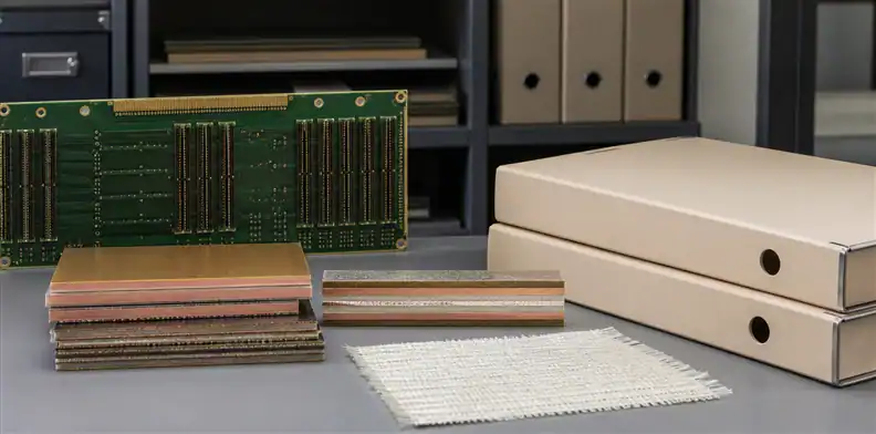
Recovery rule: Rebuild the approved baseline from controlled drawings, stackups, supplier responses, coupons, certificates, and change records—not from the material name alone.
For a sustaining design, collect the latest released fabrication drawing, native data, approved stackup, impedance table, drill chart, supplier deviation list, first-article report, material certificates, microsections, TDR results, reliability reports, and customer approvals. Identify which records describe the same revision and which belong to earlier experiments.
The qualified baseline should show:
- exact core and prepreg constructions;
- glass style and resin content where controlled;
- nominal and pressed dielectric thicknesses;
- starting and finished copper plus foil type;
- total thickness and tolerance;
- press cycles and sequential-lamination sequence;
- drill, finished-hole, plating, and backdrill limits;
- impedance geometry and coupon design;
- manufacturing source and approved alternates.
If those records do not exist, classify the next build as a controlled recovery or engineering-validation lot. Do not pretend an incomplete drawing provides the same confidence as a preserved qualification.
Use PCB incoming inspection to compare the received lot with the recovered baseline. Incoming inspection should verify observable and documented features; it cannot reconstruct an unrecorded resin system after fabrication.
Preserve impedance and loss assumptions through reorders
Electrical rule: A reorder can retain the old artwork only when the current pressed construction reproduces the approved impedance and channel behavior.
N4000-13 EP SI may be used in products whose field solver, trace dimensions, and acceptance limits were established years ago. A fabricator’s modern material library or correlation value can differ from the numeric input in the old design. That difference must be reconciled rather than hidden.
Record the Dk/Df value, test method, frequency, source revision, and solver model used in the qualified design. Then ask the current supplier what values and pressed constructions it supports. If the supplier needs a trace-width change to meet impedance, rerun the affected channel and approve the geometry revision.
| Electrical control | Reorder evidence |
|---|---|
| Impedance | Approved geometry, pressed thickness, TDR coupon and tolerance |
| Insertion loss | Route model plus representative coupon when required |
| Skew | Glass construction, routing relationship, and system margin |
| Via discontinuity | Drill/backdrill geometry and model or measurement |
For traceable TDR records, use the PCB impedance test report requirements. A report should identify lot, panel, coupon, layer pair, target, measured value, instrument or method, and disposition.
Do not “improve” a sustaining stackup only because a newer value appears more accurate. A new model can be valuable, but the change should be compared with the qualified behavior and verified before production release.
If original simulation files are unavailable, use the approved geometry and historic coupon data to create a controlled correlation model. Document its limitations. The purpose is not to claim perfect reconstruction; it is to expose how much margin exists before the supplier changes dielectric height or trace width. A targeted validation coupon can then anchor the new model to a production panel.
Connect thermal and CAF claims to acceptance evidence
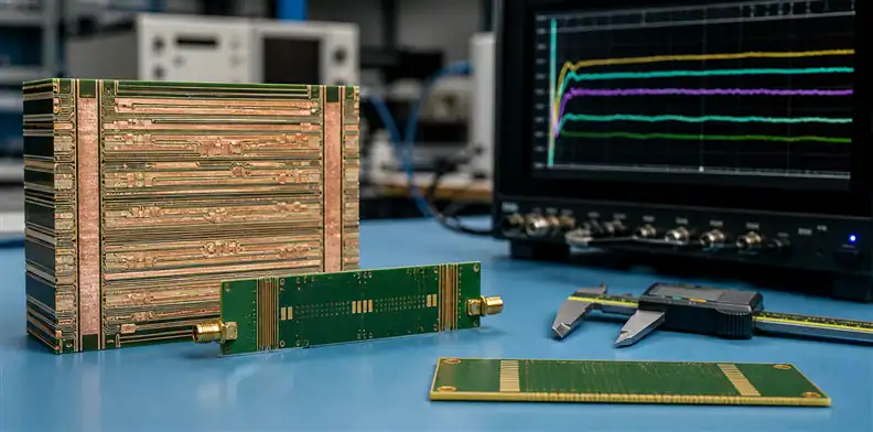
Evidence rule: Translate material attributes into tests and records that match the board’s hole geometry, assembly profile, voltage spacing, and service environment.
AGC highlights lead-free compatibility, thermal reliability, and high CAF resistance. Those are relevant to multilayer boards, but finished-board reliability still depends on pressing, drilling, desmear, plating, resin recession, cleanliness, spacing, moisture, bias, and assembly cycles.
For via reliability, define hole sizes, aspect ratios, copper thickness, acceptance microsections, thermal stress or cycling conditions, sample size, and failure criteria. For CAF risk, identify voltage, spacing, orientation, humidity, temperature, duration, and whether the design needs material-level evidence, process qualification, or a board-level test vehicle.
Do not copy an IPC slash-sheet reference into the drawing as if it specified every performance variable. Confirm the named revision during contract review and identify the additional design-specific requirements. The supplier should state whether the exact construction and source satisfy the required classification.
Use the PCB microsection report requirements for observable hole and layer evidence. Combine that report with material identity, traveler data, and the relevant reliability test; no single artifact proves the whole claim.
Decide when a replacement requires requalification
A modern ultra-low-loss material may offer better published Df than N4000-13 EP SI, but it can also change Dk, trace geometry, glass styles, resin flow, CTE, drilling, adhesion, press cycles, and supply conditions. “Better” on one axis does not preserve a qualified product.
Classify the proposed change:
- same exact construction from the approved source;
- different construction within N4000-13 EP SI;
- different source or manufacturing location;
- different material family with similar electrical targets;
- redesign with new geometry and qualification.
The first category may fit routine reorder controls. The others require an impact assessment, with depth based on the changed fields. Electrical work may include impedance, insertion loss, skew, and EMC. Fabrication work may include press, drilling, plating, and registration. Reliability work may include thermal cycling, CAF, assembly simulation, and customer-specific tests.
Use PCB material substitution approval to record the reason, affected revisions and lots, comparison data, model results, tests, approvers, and temporary or permanent scope. Do not let the substitute become the new baseline through repeated verbal exceptions.
| Change category | Minimum decision record |
|---|---|
| Construction within the same grade | Stackup delta, impedance impact, process review |
| New manufacturing source | Source identity, process comparison, first-article evidence |
| New material family | Full property comparison, model update, reliability plan |
| Geometry redesign | Revised drawing, simulation, coupon, customer approval if required |
Commercial benefits should remain visible but separate from technical acceptance. Record lead time, MOQ, panel yield, and cost beside the engineering evidence. That makes the final approval auditable without allowing schedule pressure to redefine equivalence.
Control sustaining lots, records, and deviations
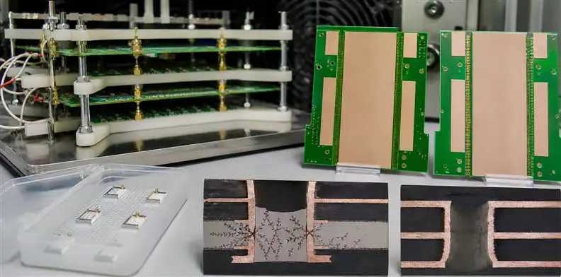
Lot rule: Every production lot should be traceable to the approved material construction and supplier stackup, even when full qualification tests are not repeated.
Define what travels with each shipment: certificate of conformance, material/lot statement, stackup or controlled-build reference, impedance report, microsection report where required, dimensional and hole results, electrical test summary, deviation approvals, and date/lot identification. Use the pre-shipment quality-record checklist to assign each record an owner and retention period.
Receiving should compare the documents with the current approved baseline. A changed foil, prepreg construction, manufacturing source, or test method is not an administrative detail. Route it through change control before accepting future lots.
Keep deviations narrow. A concession should identify the affected quantity, lot, feature, measured condition, technical rationale, and disposition. State whether the next lot returns to baseline or requires a drawing change. Otherwise a one-time exception can quietly become an uncontrolled process.
Track yield and field feedback by construction. Repeated registration, hole-wall, impedance, or warpage problems may reveal that the nominal material remained the same while the process or physical construction drifted.
Store a small golden record for each released configuration: approved stackup, representative certificate, coupon report, microsection, deviation history, and supplier contact. The record is more useful than a large unindexed archive because an auditor or new engineer can identify the baseline quickly. Keep superseded versions, but mark the effective date and part-number scope so an old approval is not applied to a newer revision.
Issue a reorder package that exposes every change
Release rule: Require a written delta response against the last approved build before accepting price and schedule as a complete quotation.
A good reorder package contains more than the old Gerbers. Include the released fabrication drawing, native data, netlist, approved stackup, impedance and drill tables, N4000-13 EP SI identity block, copper and glass requirements, coupon plan, acceptance limits, quality-document list, and prior approved deviations that still apply.
Ask the fabricator to return a delta statement with the quote. It should say whether material source, core/prepreg construction, glass, resin, foil, press route, drill process, geometry, test method, lead time, and MOQ match the last approved order. “No exceptions” should be tied to the named baseline revision.
For a product transitioning to a new supplier, use the recovered package as the input to a first-article plan. Do not expect a new fabricator to infer hidden rules from a finished sample alone.
Compare the returned delta statement with receiving and quality systems before the PO is released. If the ERP item description says only “N4000-13,” add the controlled document reference and approved source so purchasing cannot select an unrelated construction. The supplier acknowledgement should repeat that reference. This closes the gap between engineering approval and the commercial order that actually buys material.
When the records are complete, request a sustaining-build or requalification review from QueenEMS engineering. The response can separate true material constraints from legacy assumptions and identify the questions that must close before the next PO.
Reorder decision: Release only when the current AGC construction, the historical qualification baseline, and the supplier’s production plan agree—or when a documented requalification closes every difference.
Set an exit strategy for an aging qualified platform
A sustaining team should know what event will trigger migration even while N4000-13 EP SI remains orderable. Possible triggers include unavailable constructions, unacceptable lead time or MOQ, loss of an approved manufacturing source, repeated yield drift, a new compliance need, or insufficient channel margin after a system redesign.
Prepare the replacement path before a shortage. Maintain a shortlist based on the original qualification functions, not on a single Df number. Reserve representative coupons and, where possible, one known-good board for correlation. Document customer-notification and regulatory obligations, sample quantities, test duration, and the drawing revisions that a migration would affect.
This is not an instruction to redesign a stable product. It is continuity planning. By defining triggers and evidence in advance, purchasing can report a supply warning early and engineering can run a controlled comparison instead of approving a substitute under delivery pressure.
FAQ
Is Nelco N4000-13 EP SI discontinued?
AGC maintains a current product page for N4000-13 EP SI. Buyers should still confirm exact construction availability, source, lead time, and current technical documentation for the region and supplier being quoted.
What do EP and SI guarantee?
They identify the product and its intended thermal/signal-integrity positioning, but they do not replace board-specific limits. Use the current TDS and define finished-board acceptance evidence.
Can a newer lower-loss material replace it without redesign?
Not automatically. Different Dk, glass, resin, copper, thickness, and processing can change impedance, loss, reliability, and qualification status. Perform a controlled impact assessment.
What if the old approved stackup cannot be found?
Treat the next build as a baseline-recovery or engineering-validation lot. Reconstruct the best evidence available, obtain a complete current supplier stackup, and approve new electrical and reliability records.
Sources
- AGC Multi Material, N4000-13 EP SI
- AGC Multi Material, Solutions Guide
Written by the QueenEMS Engineering Team
Upload your files today · Free DFM check before production · Ship worldwide
Get your PCB prototypes in as fast as 24 hours. We handle FR4, Rogers, and hybrid boards up to 40 layers in volume production, with advanced builds subject to engineering review — free prototypes for 2–4 layer FR-4 boards, no minimum order.
Just upload your Gerber + BOM — we source every part, assemble, and inspect (AOI + X‑Ray) so you don't have to chase suppliers. Boards ship in as fast as 24 hours.