
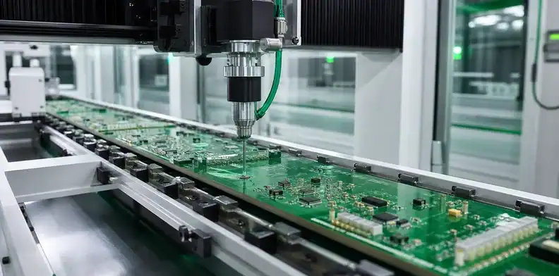
Quick Answer: Large PCB conformal coating is controllable when the entire board-and-fixture route fits, the released drawing identifies coverage and no-coat zones, and the process proves application, cure and inspection at difficult locations. Material selection alone is insufficient; support, shadows, path overlap, masking leakage and retained contamination must be addressed before production.
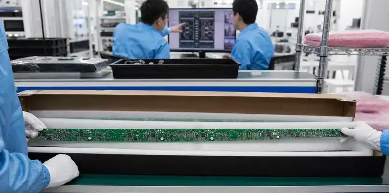
Large PCB conformal coating turns a thin protective film into a long sequence of geometric decisions. A coating head may have enough travel for the outline while a tall connector exceeds Z clearance, a fixture hides an edge, or a programmed stop leaves a dry seam halfway along the board. Cure and inspection can become the governing stations even when the applicator fits.
The conformal coating types guide covers the choice of acrylic, urethane, silicone, parylene and other material families. This page assumes that product engineering has selected or shortlisted a material and defines how an oversized assembly becomes a controlled production route.
Table of Contents
- Confirm that the complete coating route fits
- Release a coverage and keepout drawing
- Support and mask the long assembly
- Control large PCB conformal coating travel and overlap
- Cure the entire board without creating a second defect
- Inspect coverage and define rework authority
- Protect cleanliness, handling and packing
- Quote an executable coating specification
- Set repeat-order requalification triggers
Confirm that the complete coating route fits
Map loading, masking, application, flash-off, cure, cooling, inspection, demasking, touch-up and packing. For each stage, compare the populated board plus fixture against usable length, width, thickness, mass and component height. Include extraction hoods, oven racks, UV inspection frames and manual turning stations; the narrowest stage owns the route.
ANDA describes an iCoat-5 configuration for large-area applications and publishes multi-axis motion plus component-height information. Such product specifications show that specialized platforms exist, but they are not general size standards. Ask the actual factory to identify its equipment, configured travel and approved clearance with your tallest parts and support system.
Measure board, fixture and component height
Provide a top-and-bottom height map, edge handling zones, connector overhangs and cable or hardware installed before coating. Add pallet rails, masks, plugs and any rotation fixture. Confirm both the application orientation and any orientation used during flash or cure, since pooled material can move after spraying.
Board mass and stiffness affect handling. A long assembly supported only at two ends can sag toward a nozzle or rub a carrier during transfer. Define safe lift points and a mid-span support concept before the first wet board is handled.
Include cure and return handling
The coated assembly must leave the applicator without contacting wet surfaces. Check transfer clearances, rack pitch and the way boards return for a second side. If the route requires manual rotation, specify cure/handling state, ESD protection, gloves and contact-free areas.
Confirm where a temporarily parked wet assembly can rest and how its identity travels with it. A route that fits only while an operator holds the board has no repeatable handling condition and should remain on hold.
Decision point: A supplier should confirm application, flash, cure, inspection and demasking capacity—not only coating-machine XY travel.
Release a coverage and keepout drawing
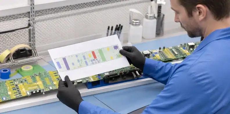
“Coat the PCB except connectors” is not production data. Release a drawing tied to the product revision and coating material. Identify side, coverage zones, no-coat zones, transitions, tolerances, edges, mounting holes, test points, heatsinks, switches, sensors, adjustable parts, mating surfaces and any area where coating may affect heat transfer or creepage intent.
| Drawing item | Production question it closes | Evidence at release |
|---|---|---|
| Material and approved substitute | Which chemistry and cure apply? | Lot identity and shelf-life status |
| Coverage boundary and tolerance | Where may the wet edge land? | Program/mask overlay |
| Connector and contact keepouts | Can capillary flow enter a mating area? | Mask check plus final inspection |
| Test pads and programming points | Must access remain after coating? | Functional access confirmation |
| Board edges, holes and hardware | Are edge coverage and drainage required? | Multi-angle visual/UV review |
| Reworkable components | Who may remove and restore coating? | Approved repair instruction |
Use dimensions from stable PCB datums, not from a component body whose placement tolerance is wider than the coating boundary. For complex geometry, provide a color-coded assembly view plus a machine-readable layer if the supplier supports it. Mark areas that require full coverage separately from areas where overspray is merely acceptable.
Power Integrations’ reliability-services flow illustrates washing, loading, double-side coating, drying, AOI and packing, and its material includes keepout diagrams. That sequence reinforces an important purchasing point: the drawing must survive every step as one controlled intent.
Resolve contradictions before quotation. A test pad cannot be both “must remain accessible” and inside an undimensioned full-board coating note. Product engineering owns the functional decision; the coating operator should not infer it.
Support and mask the long assembly
Support and masking create the physical boundary between permitted and prohibited coating. Both must remain stable during application, cure and removal without damaging components or transferring contamination.
Choose repeatable masks
Evaluate custom boots, plugs, caps, approved tapes, liquid masks, shields or fixtures against material compatibility, temperature, repeat volume and geometry. A forum thread on SMTnet highlights practical issues such as coating wicking beneath poorly sealed tape and mask materials interacting with specific coatings. Treat those observations as questions to validate with the coating and masking suppliers, not as universal recipes.
For reusable masks, define cleaning, inspection, life and replacement. Worn boots can leak gradually, creating a drifting boundary. For tape, control material, width, overlap, pressure, removal timing and residue inspection. For liquid mask, verify cure and complete removal from crevices.
Prevent support from creating blind zones
Put fixture contacts inside approved no-coat or handling areas where possible. If a contact interrupts required coverage, plan a controlled reposition or touch-up and show it on the traveler. Avoid narrow point loads on a flexible board; they can change spray distance and local coating thickness.
Simulate access around tall parts. A fixture rail can block a fan pattern or cast a shadow beyond its visible footprint. Trial the assembled fixture with a dry run, and verify nozzle/board clearance across the full travel including acceleration, rotation and tilt.
Mask inspection should be a hold point before liquid application. Record product revision, mask/fixture revision and operator check. Discovering a missing connector cap after cure converts a simple setup error into an uncertain rework decision.
Control large PCB conformal coating travel and overlap
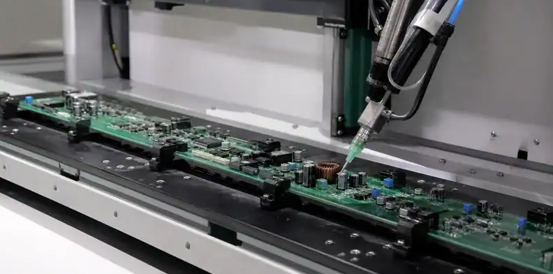
The application program must own starts, stops, turns, speed, valve state, passes and transitions. Long travel increases the chance that a refill, pressure change, viscosity drift or path boundary becomes visible in the film. Program segmentation should be deliberate and its overlap should fall in a qualified region.
Program paths around three-dimensional geometry
Use the actual populated height map to choose spray, film, needle or other approved valve behavior. Tall components create shadowed sidewalls; low-clearance parts can pull material by capillary action; exposed board edges may receive too much or too little. A head capable of tilt does not automatically produce acceptable side coverage—validate the chosen angle and clearance.
Control material preparation, viscosity where applicable, pot life, pressure, valve/nozzle, travel speed, distance and environmental conditions according to supplier instructions. If two valves or manual touch-up are used, identify which region belongs to each and how their materials and cure state remain compatible.
Own starts, stops and pass overlap
Place program boundaries where coating buildup or a slight transition is acceptable, not across fine-pitch contacts or a critical no-coat edge. Confirm that acceleration and deceleration do not change deposition. For a board longer than one working field, use fiducials or hard datums to re-establish position and inspect the overlap seam.
Apply multiple thin passes only when the material instructions and qualified process support that route. DigiKey’s practical spray guidance notes cleaning, masking and thin-layer application, but product requirements and the coating data sheet remain controlling. Avoid turning a general technique into an unsupported thickness claim.
Maintain a wet-board sample or process coupon where it genuinely represents the application. Coupons help monitor material and cure, but they cannot reveal a shadow behind a connector on the product. Product inspection remains necessary.
Program rule: Every required zone needs a named pass, verified access and accepted transition; every excluded zone needs a physical or programmed protection method.
Cure the entire board without creating a second defect
Cure is part of coating performance. Define flash time, temperature/humidity or UV/thermal conditions, duration, orientation and minimum handling state from the approved material process. A long board can experience rack-to-rack temperature differences, airflow shadowing or pooling if it is moved too soon.
Separate the UV-exposed surface from shadowed coating. MacDermid Alpha identifies a secondary moisture-cure mechanism for Electrolube UVCL. For a large assembly using that material, mark shadowed regions beneath tall components and beside fixture features on the cure map. Define permitted handling and release evidence for those regions from the approved material instructions. A fluorescent image of an accessible surface does not document completion of secondary cure elsewhere. Other products may use different cure mechanisms.
Confirm oven or cure-chamber usable dimensions with the loaded rack. Check component and label temperature limits, battery or sensor restrictions, adhesives and plastics. If room-temperature cure is used, control dust, spacing, airflow and the time before masking removal, inspection or packing.
Instrument the first route where product risk warrants it. Temperature indicators or thermocouples at representative hot and cold locations can demonstrate what the assembly experienced, while material/process coupons can support cure verification. Choose evidence that corresponds to the material supplier’s instructions and project acceptance plan.
Consider both sides. Coating one side and turning too early can create fixture marks, runs or transferred contamination. If the first side is fully cured before the second, confirm intercoat timing and handling. If both sides are processed in a shorter sequence, qualify contact-free support.
Do not use cure heat to “dry out” an assembly whose cleaning status is uncertain. Trapped solvent or water may interact with the coating, and contamination can cause dewetting or long-term leakage. The released traveler should require an approved cleanliness/dryness state before masking and application.
After cure, let the assembly cool in its support before measuring shape or removing a tight fixture. Sudden release can introduce mechanical stress or crack a brittle film at flexing locations. Record any board-shape acceptance separately from coating appearance.
Cure check: Release the assembly only when the documented cure condition, handling state and product restrictions agree for the entire loaded board.
Inspect coverage and define rework authority
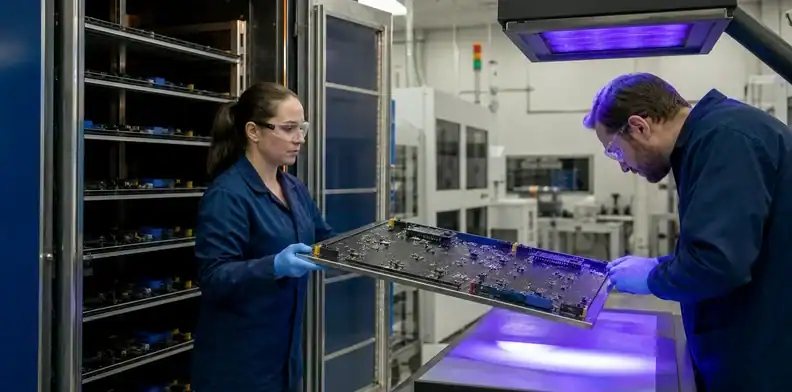
Inspection should use the selected material’s visible, fluorescent or other characteristics and the drawing’s acceptance criteria. Review normal lighting and UV lighting when the material contains a compatible tracer. Rotate the large board or use a fixture so inspectors can see edges, vertical faces, beneath overhangs and transition lines without flexing the assembly.
Separate presence from thickness evidence
UV response can help locate missed areas, mask leakage and transitions; it does not automatically measure dry-film thickness or prove cure. Define where and how thickness is assessed, whether wet-film checks, coupons, non-destructive methods or approved destructive measurements apply, and how their locations represent the product.
Document bubbles, pinholes, dewetting, cracks, runs, pooling, foreign material, orange peel where relevant, edge coverage and overspray according to the governing requirements. Avoid rejecting harmless visual variation or accepting a functional gap based solely on color intensity.
Close mask leakage and missed areas
For each defect, define whether cleaning, local removal, touch-up, recoating or scrap is allowed. The repair instruction should name compatible removal methods, component protection, surface preparation, reapplication, cure and reinspection. Limit the number or area of repairs if repeated processing could damage the coating or assembly.
Record defect location by board coordinate or reference designator, plus product serial/lot, material batch, program and disposition. Trend leakage by mask feature and dry spots by program path. That data improves tooling instead of normalizing repeated touch-up.
Link coating inspection to the broader large PCB inspection evidence plan, especially when dimensional shape, connectors or test access must be rechecked after cure.
Protect cleanliness, handling and packing
Coating can seal contamination against the assembly. Define the soldering-to-cleaning window, approved cleaning process, dryness check and maximum clean-to-coat exposure. The PCB cleanliness testing requirements explain how acceptance should connect to product risk rather than one universal visual rule.
After cleaning, prevent fingerprints, dust, silicone and unapproved marker or adhesive contact. Use gloves and designated support areas. Masking materials and reusable fixtures need their own contamination control because they repeatedly touch the product near a sensitive wet process.
After cure and inspection, confirm that connector caps and temporary masks are removed, that no residue remains, and that required test access is restored. Perform final electrical or functional checks required by the process plan. If coating changes thermal behavior around hot devices, product validation—not the coating operator—must own that assessment.
Pack the board so cushioning contacts approved mechanical areas and does not abrade the film. A large flexible assembly can rub against a bag or insert during transport. The oversized PCB packaging guide provides the mechanical shipment framework; add coating-specific cure-age, surface-contact and humidity requirements.
Retain material lot, shelf-life/in-use status, program, fixture/mask revision, cure record, inspection results, rework and product traceability. These records make a repeat order reproducible and allow a change assessment when material or equipment changes.
| Route record | What it preserves | Review trigger |
|---|---|---|
| Clean/dry and mask hold | Surface condition and protected zones | Exposure window or mask revision changes |
| Application and cure record | Material, program, passes and cure state | Equipment, material or recipe changes |
| Inspection/rework log | Coverage exceptions and authorized repair | Repeat leakage, missed area or touch-up |
Record rule: Do not reuse a coating baseline after its material, masks, fixture, application path or cure route changes without an impact review.
Quote an executable coating specification
Send the controlled assembly drawing, 3D/height information, finished dimensions and mass, coating material and approved substitute, coverage/keepout drawing, required thickness or performance basis, cleanliness state, cure constraints, inspection criteria, rework authority, quantity and records. Identify components sensitive to chemistry, heat, vacuum or UV.
Ask the supplier to return:
- usable dimensions and height at application, cure and inspection;
- board support, handling and two-side sequence;
- masking method and reusable-tool ownership;
- application valves/passes, program boundaries and touch-up areas;
- material preparation, process controls and traceability;
- flash/cure route and product-relevant evidence;
- coverage/thickness inspection and declared blind locations;
- repair method, change triggers and shipment records.
Require a first-article board or representative qualification sample when shadows, selective boundaries, new materials or a novel fixture create risk. Define who approves coating appearance and who approves electrical/mechanical product performance.
Package the manufacturing data with the large PCB RFQ file guide. Separate one-time programming/masks, qualification evidence and recurring coating cost; otherwise suppliers may quote different scopes under one line item.
Quotation request: For coating feasibility, attach the populated height map, keepout drawing, selected material, cleanliness requirement, cure restrictions and inspection deliverables on the QueenEMS Large Format PCB page. The returned proposal should expose every manual touch-up and coverage exception from masking through final cure.
Set repeat-order requalification triggers
A repeat order is not automatically the same coating process. Review material supplier or formulation, viscosity control, shelf-life handling, masks, fixture contact, valve/nozzle, program, flash/cure equipment, cleaning route, component height and acceptance method. Link each change to the zones or evidence it can affect.
| Change class | Targeted recheck | Full-route concern |
|---|---|---|
| Material or cleaner | Compatibility, wetting, cure and adhesion | New chemistry interaction |
| Mask, fixture or program | Boundaries, shadows and pass overlap | Changed geometric coverage |
| Cure or inspection system | Cure state and detection capability | Previous evidence no longer comparable |
Retain an approved first-lot image set and process record so quality can compare changes against a real baseline. If the new condition can alter coverage, cure or product function outside the checked region, reopen the complete qualification instead of approving a narrow trial.
Change check: Requalify the full route when a proposed change can move coating boundaries, alter cure or invalidate the existing inspection evidence.
FAQ
Can an oversized PCB be selectively conformal coated?
Yes, when the actual application platform, fixture, cure equipment and inspection station fit the populated assembly. Confirm the complete route rather than relying on one machine’s advertised travel.
Which areas should remain uncoated?
Product engineering should define connectors, contacts, switches, test/program points, adjustable features, grounding interfaces, heatsinks and other functional keepouts on a released drawing. The list is product-specific.
Does UV inspection prove coating thickness?
Usually it is most useful for visible presence, missed areas and boundary leakage when the material fluoresces. Thickness needs an approved measurement or coupon method; UV brightness alone should not be treated as a universal thickness gauge.
Must a large PCBA be cleaned before coating?
Follow the approved flux, coating and reliability process. If cleaning is required, validate removal and complete drying. Coating over uncontrolled residue or trapped liquid can create long-term risk.
How should coating rework be documented?
Record location, reason, removal/preparation method, material, cure, reinspection, authorization and affected serial/lot. Repeated repairs should trigger process or tooling review.
Sources
- Power Integrations Reliability Services process flow
- DigiKey TechForum conformal-coating spray guidance
Written by the QueenEMS Engineering Team
Upload your files today · Free DFM check before production · Ship worldwide
Get your PCB prototypes in as fast as 24 hours. We handle FR4, Rogers, and hybrid boards up to 40 layers in volume production, with advanced builds subject to engineering review — free prototypes for 2–4 layer FR-4 boards, no minimum order.
Just upload your Gerber + BOM — we source every part, assemble, and inspect (AOI + X‑Ray) so you don't have to chase suppliers. Boards ship in as fast as 24 hours.