
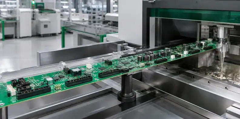
Quick Answer: Large PCB selective soldering needs a machine-and-tooling route that fits the populated assembly, supports its span and heats its full thermal mass before each joint meets the mini-wave. Qualify flux access, nozzle clearance, component retention and a populated thermal profile together; a bare-board size promise is not enough.
Large PCB selective soldering is often requested after the design already contains connectors, relays, transformers or mixed-technology parts that cannot pass through ordinary SMT reflow. The technical risk is not simply whether molten solder touches every lead. A long board can cool unevenly, bow away from the nozzle, shadow flux, or collide with support hardware while the program still completes.
For an oversized through-hole assembly, the selective-solder route must fit the loaded board and deliver a suitable thermal profile at the joints. The selective-versus-wave soldering comparison helps with the initial process choice. Check the equipment limits across the assembly line before quoting a route that depends on one machine or carrier.
Table of Contents
- Release the board only after the full route fits
- Design support around the soldering path
- Preheat the complete thermal mass
- Give flux and nozzles usable access
- Retain components and preserve datums
- Prove large PCB selective soldering at difficult joints
- Control production evidence and changes
- Quote a buildable selective-solder route
Release the board only after the full route fits
Begin with the finished assembly, not the routed PCB. Record the board outline, carrier or frame, thickness, mass, top and bottom component heights, edge-clear zones, leading edge and center of gravity. Then walk those values through loading, fluxing, preheat, soldering, cooling and unloading. A board may fit the solder module and fail at a narrower conveyor, a lower preheat tunnel or a manual transfer fixture.
Ersa’s published selective-soldering range illustrates why configuration matters. Its product overview lists a VERSAFLOW 3/66 class around 610 x 610 mm and XL options reaching much longer formats in one dimension. Those are equipment examples, not standard industry limits and not automatic confirmation of a specific QueenEMS route. The responsible factory must name the actual model, configured width, available travel, carrier allowance and component-height window.
Measure the assembly-plus-tooling envelope
Add every feature that moves with the product: pallet rails, hold-downs, board clamps, masks, thermocouple wires during profiling and any temporary component-retention tooling. For a double-sided assembly, verify underside parts against nozzle, fluxer, conveyor and support clearance. Record the approved orientation on the drawing.
Mass and balance affect transfer even when dimensions fit. A board that overhangs a narrow carrier can tip, bounce or drag. Ask who owns loading and whether the process remains inline, uses a shuttle, or requires controlled manual transfer.
Find the first hard limit
Build a station table with the usable values confirmed by production engineering. The smallest width, length, height, mass or travel allowance governs the route. Mark any soft limit that can be changed with tooling separately from a fixed machine envelope.
Record the unsuccessful orientation as well as the selected one when the choice is close. That note prevents a repeat-order operator from rotating the assembly into an apparently wider but thermally or mechanically invalid path.
Decision point: Do not release material until one reviewed route includes the populated board, carrier, transfer method and every soldering stage.
Design support around the soldering path
Support has two jobs that can conflict: keep the large board within an acceptable shape, and leave flux and solder access open. A solid plate may control sag but block bottom-side components, spray, drainage and the mini-wave. Sparse pins may provide access but concentrate load or allow the joint area to move relative to the nozzle.
Map the bottom side into support-permitted, process-access and keepout zones. Put adjustable contacts beneath structurally suitable areas, not beneath fragile components, vias that require inspection, or the exact THT barrels being soldered. Confirm contact at process temperature; a support that works on a cold board may lose contact as the assembly expands and bows.
| Tooling question | Evidence needed | Typical risk if omitted |
|---|---|---|
| Where is mid-span load carried? | Support drawing and loaded-board trial | Board-to-nozzle distance changes |
| Which joints need bottom access? | Nozzle/flux path overlay | Tooling shadows the process |
| What restrains board edges? | Clamp type and allowed keepout | Copper/component collision |
| How do underside parts clear? | Height map against all contacts | Crushed component or unstable seating |
| Where does solder drain? | Orientation and exit-path review | Bridges, icicles or retained solder |
If a pallet is required, include its material, thickness, thermal mass and revision in the process definition. It changes both board shape and preheat response. Separate “fixture fits” from “fixture has been thermally qualified.”
Use repeatable datums so the board returns to the same nozzle coordinate after loading variation. On a very long board, local fiducials near solder groups may reduce error from expansion and global distortion. Tooling should not rely on forcing a warped board flat unless product engineering approves that load.

Preheat the complete thermal mass
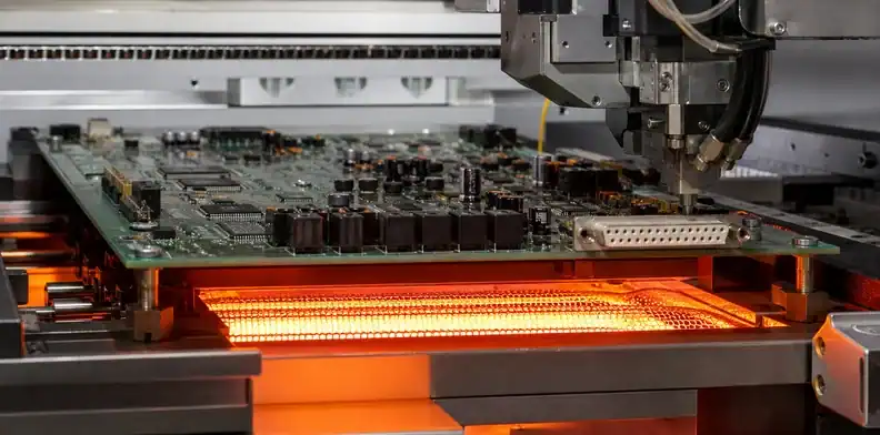
Selective soldering applies intense local heat after fluxing. Large copper planes, heat sinks, connectors and long spans pull energy away at different rates. Without controlled preheat, operators may compensate with extra dwell or higher pot temperature, increasing laminate, mask, component and intermetallic risk while still leaving a cold barrel.
Nordson describes full-surface IR preheat with closed-loop pyrometer control for large PCBAs. The engineering lesson is broader than one machine: measure the assembly temperature rather than assuming that heater settings create a uniform board condition. The approved flux and component limits remain the governing sources.
Locate hot and cold profile points
Instrument a populated profile vehicle in the intended carrier. Place thermocouples near high-copper THT joints, low-mass regions, sensitive components, the leading and trailing ends, and any span that sits differently on the support. Include the joint or lead temperature measurement method needed to verify the soldering event.
Do not select points only because they are easy to attach. Explain which risk each channel represents. Record attachment method, channel/location photo, data logger, sample rate, program and board orientation.
Control ramp and recovery
Review temperature before flux activation, before nozzle contact, through solder exposure and during cooling. Map checks to representative joints near the beginning and end of the program and to a copper-rich joint that is difficult to heat. Record temperature immediately before nozzle contact under the intended support and waiting conditions. For multiple preheat zones, identify which controls affect the measured board response.
Hentec/RPS explains that high-thermal-mass boards may require larger nozzles or longer contact because heat arrives through the flowing solder. Use this mechanism to investigate a cold late-stage joint. Check preheat retention, nozzle access and the component’s exposure limit before increasing dwell across the whole program.
Compare the measured profile with flux, solder alloy, laminate, component and customer requirements. The detailed large PCB thermal profile guide explains hot/cold-point selection for long assemblies; apply the same evidence discipline to this selective process rather than copying an oven recipe.
Profile check: Approve the program only when the populated vehicle proves hot and cold joints, sensitive parts and repeated-cycle recovery inside their governing limits.
Give flux and nozzles usable access
The nozzle path is three-dimensional. A joint can lie inside the XY work area while a neighboring connector, heat sink or carrier wall prevents approach. Create a bottom-side overlay containing THT targets, nozzle diameter, travel path, flux pattern, support contacts, keepouts and board edges. Review it before tooling manufacture.
Map keepouts before programming
For each solder group, document available approach angle, clearance to SMT parts, board-edge distance and permitted solder contact. Choose nozzle geometry from the actual lead pattern and surrounding features. If an off-axis or custom nozzle is proposed, confirm how it affects repeatability, maintenance and spare-tool availability.
Flux must reach the intended barrels without coating protected areas or pooling in cavities. Define flux type, application pattern, quantity-control method and verification. Overspray onto connector contacts, test points or downstream coating surfaces is a product issue, not merely a cosmetic variation.
Protect drainage and solder separation
Program approach, contact, dwell and separation so solder drains away rather than forming bridges or icicles. Board orientation and local slope matter on a large assembly. Tall protruding leads can disturb the mini-wave or retain solder; lead-length limits should exist in the component and assembly data.
Review adjacent thermally sensitive items and bottom-side adhesives. A joint group may require a different path or sequence to reduce cumulative heating. Avoid solving access by removing structural supports unless the loaded-board shape has been rechecked.
Access rule: Every programmed joint group needs a reviewed nozzle corridor, flux corridor, support condition and drainage path.
Retain components and preserve datums
Through-hole components can lift, tilt or float before solder freezes. Long bodies and heavy connectors add leverage, while a large flexible board moves beneath them. Decide whether lead clinch, dedicated hold-downs, temporary fixtures, adhesive, insertion-force retention or another approved method will maintain seating.
The retention method must not deform the component, obscure inspection or trap flux. A top fixture should clear SMT components and distribute load over safe surfaces. If selective soldering occurs after other hardware is installed, include that hardware in the mass, access and thermal model.
Establish inspection criteria for seating, perpendicularity, connector datum and board-to-component gap before soldering. A correctly filled barrel does not rescue a connector that hardened in the wrong position. Where multiple connectors must mate to an enclosure, use the datum strategy from the large PCB connector-alignment guide and verify the assembly in representative hardware.
Local fiducials, tooling holes or hard stops should reference the same coordinate intent used to inspect connector position. Thermal expansion can change global dimensions during processing, so avoid over-constraining the board. One round datum and one directional slot often provide more predictable restraint than multiple rigid pins, subject to the mechanical design.
After cooling, release hold-down force in a defined sequence and recheck seating and board shape. A fixture that hides movement until removal creates a late surprise. Capture any manual correction as rework, not as an invisible part of normal assembly.
Prove large PCB selective soldering at difficult joints
Choose the first-article evidence from the hardest features, not from an easily visible connector near the board edge. Include the coldest high-copper barrel, the tightest nozzle clearance, the most heat-sensitive neighbor, the final joint after thermal recovery and any connector with critical seating.
Inspect barrel fill and wetting
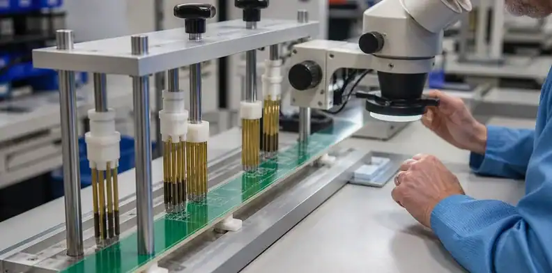
Use the project acceptance source to evaluate solder-source-side and destination-side wetting, vertical fill where applicable, lead and land condition, bridges, icicles, disturbed joints, mask damage and contamination. Visual inspection may need magnification and multiple views. Destructive sectioning should use approved coupons or designated samples and must be quoted in the quantity plan.
Where visible evidence cannot close the question, allocate X-ray, electrical test or controlled process evidence. Do not claim that one method proves all internal barrel conditions. Link photographs and results to the board serial, joint group, program and nozzle revision.
Challenge repeats after thermal recovery
Run enough consecutive boards or repeated cycles to expose heater recovery, solder-level stability, flux replenishment and tooling temperature. Compare the first and later assemblies at the same difficult joints. A single perfect pilot after an extended warm-up does not prove a repeatable production window.
Record defects and false alarms by joint group. If the process needs hand touch-up, identify the cause, approved repair method and reinspection. An extensively repaired first article cannot approve the untouched initial program.
Use staged holds from the large PCB first-article plan when tooling and profile risk are high. Release only the quantity supported by the current evidence.
Control production evidence and changes
The process traveler should identify product revision, board/lot, carrier and support revision, flux material and lot, solder alloy, machine/program/nozzle, preheat recipe, profile approval, inspection results, rework and operator or line identity. Preserve actual values where the equipment records them, not only a pass flag.
Define response limits for board temperature, solder pot condition, flux process control and joint findings. A limit excursion should identify affected boards and the required hold or reinspection. Keep program changes under revision control so production cannot silently alter dwell or path to chase a local defect.
Change assessment should cover PCB stack-up/copper, component or connector substitution, carrier/support, flux, solder alloy, nozzle, machine, preheat configuration, program sequence and acceptance criteria. Decide whether the change requires documentation only, targeted requalification or a new first article.
Trend joint defects by location. A cluster near the far end can indicate thermal or support variation; repeat bridging between the same pins can indicate lead length, nozzle choice or drainage. Pair the defect data with actual profile and tooling revision before assigning cause.
Shipment evidence should match the purchase requirement. A concise package may contain approved profile summary, first-article photos, defect/rework summary and certificate references. A high-reliability build may need detailed measurements or destructive evidence. Define this before the PO.
| Controlled item | Repeat-lot evidence | Trigger for review |
|---|---|---|
| Carrier, support and nozzle | Revision and setup confirmation | Tooling repair or geometry change |
| Flux, alloy and preheat | Material/recipe identity | Supplier, chemistry or heater change |
| Difficult-joint result | Inspection and rework summary | Defect trend or acceptance change |
Record rule: Hold affected boards when tooling, materials or profile values no longer match the qualified selective-soldering baseline.
Quote a buildable selective-solder route
Provide assembly Gerber/ODB++, drawing, BOM/AVL, centroid, finished dimensions, thickness, mass, top/bottom height maps, THT lead and hole data, connector seating requirements, flux/alloy restrictions, acceptance standard, planned volume and expected records. Identify bottom-side SMT parts and components that cannot tolerate wash, flux or heat exposure.
Ask the supplier to return:
- actual machine and configured board-plus-carrier envelope;
- load/transfer orientation and any manual handling;
- carrier, support and component-retention concept;
- preheat technology, profile-vehicle plan and thermocouple risks;
- nozzle list, access exceptions and proposed design changes;
- flux, solder alloy and process-control method;
- first-article quantity, inspection and destructive evidence;
- rework authority, change triggers and repeat-order records.
Require exceptions in writing. If one connector needs hand soldering, the quotation should state why, how thermal mass is controlled and what evidence applies. This is more useful than a general “selective soldering available” line item.
Use the large PCB RFQ package guide to keep product and tooling data controlled. Separate one-time engineering/tooling, qualification samples and recurring production cost so suppliers can be compared on the same route.
Quotation request: Send the complete populated envelope, bottom-side access map, THT joint groups, flux/alloy requirements and evidence checklist through the QueenEMS Large Format PCB page. Request a machine-specific support, preheat and nozzle plan before authorizing the lot.

FAQ
How large can a PCB be for selective soldering?
Published machines span different widths and lengths, including specialized longboard configurations. The usable answer depends on the exact model, carrier, component height, mass, orientation and every transfer stage.
Does selective soldering always need a carrier?
No. A stiff assembly with adequate edge support may run without one, while a long or flexible board may need a carrier or local supports. The fixture decision must preserve nozzle and flux access.
Why is full-board preheat important?
It reduces the temperature difference between high- and low-mass regions before local solder contact. The populated profile must still prove that sensitive parts and target joints remain inside approved limits.
Can a tall connector be selectively soldered near the board edge?
Possibly, if the fluxer, nozzle, support and conveyor have enough three-dimensional clearance and the connector remains seated. Review a real access overlay instead of relying on XY coordinates.
What should the first-article report contain?
At minimum: product and program identity, tooling/nozzle, populated thermal profile, difficult-joint inspection, connector seating, defects/rework and the approval that releases the next quantity.
Sources
Written by the QueenEMS Engineering Team
Upload your files today · Free DFM check before production · Ship worldwide
Get your PCB prototypes in as fast as 24 hours. We handle FR4, Rogers, and hybrid boards up to 40 layers in volume production, with advanced builds subject to engineering review — free prototypes for 2–4 layer FR-4 boards, no minimum order.
Just upload your Gerber + BOM — we source every part, assemble, and inspect (AOI + X‑Ray) so you don't have to chase suppliers. Boards ship in as fast as 24 hours.