
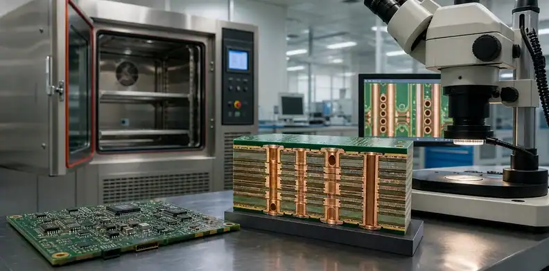
Quick Answer: PCB Z-axis CTE is the through-thickness expansion of the dielectric, and it matters because copper plated holes and vias must stretch with the board during thermal excursions. Select materials using the full reliability condition: expansion below and above Tg, total board thickness, hole structure, copper plating, moisture exposure, and the actual thermal cycle. High Tg alone does not close a via-reliability decision.
- Z-axis expansion loads plated through holes and microvias differently from in-plane expansion.
- The transition above Tg can change the stress condition sharply.
- Material selection must be reviewed with board thickness, via geometry, plating, and thermal exposure.
- Qualification evidence should identify the actual construction and test boundary.
PCB Z-axis CTE is often reduced to a datasheet number during material selection. That is too narrow for a board with demanding thermal cycling, thick multilayer construction, dense vias, or high-temperature assembly. The material expands through its thickness while copper structures resist that movement. Repeated strain can concentrate in plated-hole barrels, microvia interfaces, and other geometry-dependent locations.
The laminate family overview is the right starting point for material families. This article turns Z-axis CTE into a release decision: which related inputs matter, what evidence should be requested, and how to keep a material substitution from changing reliability without review.
Table of Contents
- What Z-axis CTE measures on a finished board
- Why Tg changes the reliability discussion
- Which via structures are most sensitive
- How board thickness and stack-up raise strain
- What moisture and assembly heat add to the risk
- How to compare material alternatives
- Which evidence should support production release
What Z-axis CTE measures on a finished board
Z-axis CTE measures how much a dielectric expands perpendicular to the PCB surface as temperature changes. This direction is significant because plated through holes, buried vias, and microvia structures cross or terminate within the board thickness. Copper does not expand in the same way as a resin-and-glass dielectric, so thermal cycles create a mechanical mismatch that the interconnect has to survive.
The value belongs to a material construction and test condition. A finished multilayer board adds copper distribution, pressed prepreg, holes, plating, and local geometry. For that reason, a low-looking material value is helpful but incomplete. It should be read with the construction that will be built and the temperature range that the product, assembly process, or qualification test will impose.
A published study of copper-wrap specifications for PTH reliability models how laminate and fill-material choices interact with the plated interconnect during thermal cycling. It is relevant to the material-and-interconnect interaction discussed here, not a universal Z-axis limit; the final release still depends on the actual construction and test scope.
Reliability rule: A material data sheet can support a shortlist; only the finished construction can support a production release decision.
Why Tg changes the reliability discussion
Tg, or glass-transition temperature, marks a change in polymer behavior. Above that range, many laminate systems expand more rapidly through the thickness than they do below it. A high Tg can therefore be valuable when assembly or operation would otherwise push the dielectric into a higher-expansion region. It is not a substitute for looking at the actual Z-axis behavior and total expansion.
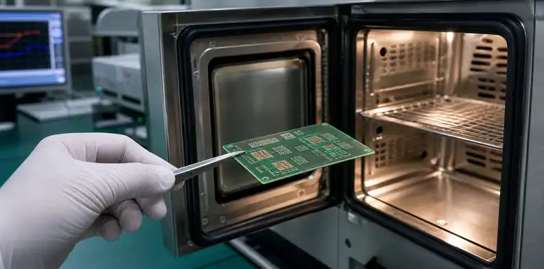
The relevant temperature is not just the product’s normal operating point. Consider lead-free reflow, rework, burn-in, thermal cycling, hot spots, and any qualification profile. A board may spend limited time at peak assembly temperature, but those excursions can still matter if via geometry and material system leave little margin.
| Question | Why it changes material choice | Evidence to request |
|---|---|---|
| What is the highest assembly exposure? | Determines whether the construction crosses a risky range | Reflow profile or process temperature window |
| What is the operating cycle? | Sets repeated strain condition | Environmental or product thermal-cycle profile |
| What is Tg and Z-axis behavior? | Shows transition and expansion context | Current material data and construction |
| What is the board thickness? | Converts expansion rate into displacement | Released stack-up |
The BT substrate datasheet article shows why material values need their test context. Apply the same discipline to CTE data: preserve the method, range, and construction behind the result.
Temperature check: Compare the proposed material range with both assembly exposure and the product’s repeated operating cycle.
Which via structures are most sensitive
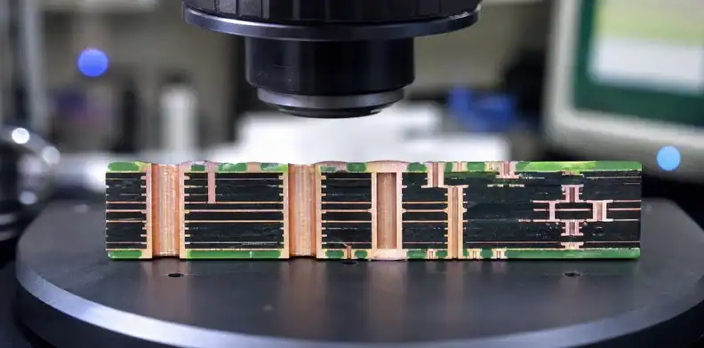
Through holes, buried vias, and laser-drilled microvias do not see strain in the same way. A plated through hole spans the board thickness, so thicker boards and greater through-thickness movement can raise barrel strain. A microvia is shorter, but its interface at the target pad and its local dielectric construction can be highly sensitive to material, plating, fill, and sequential-lamination conditions.
The design review should identify structures that are both critical and hard to rework: high-aspect-ratio through holes, stacked microvias, via-in-pad under large BGA packages, and vias that connect thermally stressed layers. A generic material note is insufficient for these features. The supplier needs the approved stack-up, via spans, drilling or laser assumptions, and acceptance evidence.
For microvia-specific constraints, use the HDI build-up reference and the PCB laser drilling acceptance article. Those pages cover geometry and fabrication evidence; Z-axis CTE adds the material-side loading condition.
How board thickness and stack-up raise strain
Expansion rate becomes more consequential as the dielectric path becomes thicker. A thick multilayer board can move farther through its thickness over the same temperature change than a thin board, while the copper barrel or interconnect geometry is expected to remain intact. Layer count alone is not enough; the stack-up must show total thickness, core/prepreg distribution, copper schedule, and any asymmetric construction.
Symmetry helps because it reduces competing mechanical forces that can add warpage or local stress. Mixed material systems require extra discipline. A high-speed core, a standard prepreg, a heavy copper power region, and sequential buildup may all be justified, but their combined expansion and press behavior should be reviewed rather than approved as independent notes.
The stack-up construction reference shows why a material family name is not enough to describe a finished multilayer dielectric. For reliability work, add Z-axis properties and the intended thermal exposure to the same stack-up review.
Construction call: Treat a via geometry change and a dielectric change as one reliability decision when they occur on the same buildup.
What moisture and assembly heat add to the risk
Moisture can change the response of resin systems during rapid heating and can amplify concerns around delamination, voiding, and interconnect stress. The right action is not to invent a universal bake profile. Instead, define storage, handling, and assembly conditions for the named material and follow the material supplier’s documented limits.
Assembly heat also needs a clear boundary. A board that sees one controlled reflow is different from a product expected to tolerate repeated rework or long high-temperature dwell. The RFQ should say whether qualification includes reflow simulation, thermal cycling, or both, and who decides if the proposed material construction differs from the one evaluated.
For the practical storage side, use the prepreg handling and stack-up reference. Keep its scope separate from this article: storage control protects the material condition; Z-axis CTE review identifies the thermomechanical load the finished interconnect must survive.
How to compare material alternatives
Compare alternatives as construction packages. Ask for the candidate core and prepreg, Tg, relevant Z-axis behavior, pressed thickness, copper schedule, and the layers or via structures affected. A substitution may be reasonable for an early prototype but unacceptable for a board whose via reliability has been qualified around a different construction.
Avoid a simplistic rule such as “higher Tg always wins.” A material can have a favorable Tg but an unsuitable expansion, moisture, processing, or electrical profile for the actual board. Conversely, a well-qualified construction may be suitable even when another material advertises a more attractive single number. The accepted choice depends on the named risk and evidence plan.
The PCB material substitution approval process is the place to record a proposed change. Require the supplier to say whether it affects hole reliability, stack-up dimensions, impedance, or qualification evidence before purchasing approves cost or availability.
One useful comparison format separates material properties from construction effects. In one column, list the supplier’s stated Tg, Z-axis behavior, moisture condition, and relevant material revision. In another, list the actual board thickness, via spans, plating target, buildup sequence, and planned test. The first column describes a candidate; the second shows whether the candidate has been applied to the product that will be released.
Ask what was held constant when an alternative was qualified. If the supplier changed both laminate and plating chemistry, the test cannot isolate the material effect. That does not make the build invalid, but it means the approval should be for the entire construction package rather than for a supposedly interchangeable laminate alone.
Which evidence should support production release
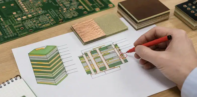
Build the evidence plan around the failure mode, not around a familiar document name. A board dominated by plated through-hole fatigue may need a thermal-cycle method and a representative cross-section. A buildup-heavy design may need microvia-specific construction evidence. A product with a demanding rework profile may require the assembly exposure to be represented as well. The release record should say which concern each item addresses.
Production release should preserve the accepted stack-up, material revision, via construction, and reliability evidence. Depending on risk, the package may include a supplier construction table, microsection requirements, thermal-cycle or interconnect-stress testing, coupon data, and a review of any material substitute. The important point is traceability: later lots must be compared with the construction that was actually qualified.
Use a microsection when it answers a defined construction question, such as plating distribution, dielectric condition, fill, or interface quality. Use a reliability test when it represents the expected loading sufficiently to support the decision. A report with no stated board construction cannot prove much about a production lot.
The PCB microsection report requirements can help define the documentation request. For a high-risk board, connect that report to the exact via types and material layers that matter rather than asking for a generic cross-section.
Define the acceptance consequence before the sample is tested. A pass can authorize the named construction; a failure can trigger a revised material, board thickness, plating, or via structure; an inconclusive result can require more representative test conditions. This matters because a material review becomes unmanageable when the same result is used later to support several unrelated board changes.
For incoming quality, retain the lot identity and stack-up revision with the report. A later reliability concern can then be traced to a real construction instead of an assumed family name. That traceability is the practical value of a Z-axis CTE review.
For release, compare the material listed in the quote, approved stack-up, and CAM response. A mismatch is a hold point because a material or construction change can move the board outside the scope of its plated-through-hole or microvia evidence. If a coupon covers only one via geometry, record that limit instead of treating it as proof for every interconnect on the product.
| Interconnect | Primary material concern | Useful release evidence |
|---|---|---|
| Plated through hole | Through-thickness expansion during thermal cycling | Representative construction and interconnect test scope |
| Stacked microvia | Buildup dielectric and interface loading | Buildup sequence, microsection plan, and target-via definition |
| Mixed via region | Different local thickness and copper conditions | Marked drawing region and supplier CAM response |
Change check: Reopen the reliability review when a substitute changes the pressed construction, via span, copper schedule, or expected thermal exposure.
QueenEMS can review a via-reliability package when you provide the stack-up, board thickness, via spans, copper schedule, anticipated assembly profile, operating cycle, and proposed material alternatives. The review can separate a quote assumption from a construction that has enough defined evidence to release. Use the QueenEMS contact page for that review.
FAQ
Is high Tg enough to prevent via failures?
No. High Tg can help keep a laminate out of a higher-expansion state, but Z-axis behavior, board thickness, copper plating, via geometry, and thermal exposure still control the final risk.
Are microvias less sensitive than through holes?
Not automatically. Microvias have shorter spans but can concentrate stress at interfaces and depend strongly on buildup dielectric, plating, fill, and sequential-lamination control.
Should a material substitute trigger another reliability review?
Yes when it changes the qualified construction. Review the affected layers, pressed thickness, Z-axis behavior, and evidence plan before the substitution is released.
What is the most useful first document for this review?
The released stack-up. It links material properties to board thickness, via spans, copper schedule, and the actual construction the supplier intends to build.
Sources
- IPC, Reliability Testing of PWB Plated Through Holes in Air-to-Air Thermal Cycling
- A Study on Effects of Copper Wrap Specifications on Printed Circuit Board Reliability
Written by the QueenEMS Engineering Team
Upload your files today · Free DFM check before production · Ship worldwide
Get your PCB prototypes in as fast as 24 hours. We handle FR4, Rogers, and hybrid boards up to 40 layers in volume production, with advanced builds subject to engineering review — free prototypes for 2–4 layer FR-4 boards, no minimum order.
Just upload your Gerber + BOM — we source every part, assemble, and inspect (AOI + X‑Ray) so you don't have to chase suppliers. Boards ship in as fast as 24 hours.