
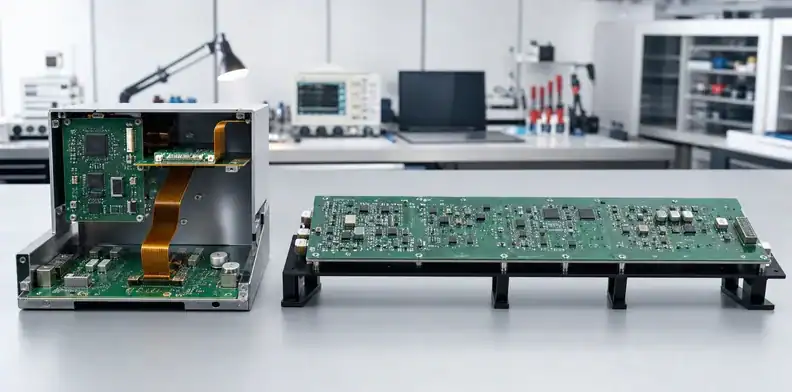
Quick Answer: Choose a large rigid PCB when the electronics occupy one supported plane and low-cost fabrication, straightforward test and field replacement matter most. Choose rigid-flex when one continuous circuit must fold across several planes and eliminating cables or mating connectors provides enough space, assembly or reliability value to justify a more specialized stack-up and qualification route. Compare the complete product architecture, not bare-board prices.
A long rigid board often begins as the simplest way to keep all electronics on one continuous circuit. The decision changes when the enclosure bends around a battery, display, sensor or housing wall. Define the baseline before assigning savings: one continuous rigid PCB may already contain no internal cables or board-to-board connectors. Rigid-flex can remove only interfaces that actually exist in the compared architecture. If separate rigid modules and cables are also evaluated, list them as a distinct third option with their own assembly and service costs.
This comparison is narrower than one large PCB versus multiple rigid boards. It asks whether a continuous large electrical design should stay flat and rigid or become an integrated folded rigid-flex assembly.
Table of Contents
- Start with the product’s physical envelope
- Compare continuous routing and interconnects
- Compare mechanical support and bend control
- Plan different assembly and test routes
- Balance reliability against serviceability
- Model total system cost without multipliers
- Choose by product and revision stage
- Prepare a comparable RFQ
- Record the architecture release decision
Start with the product’s physical envelope
Geometry is the first decision. A large rigid PCB works best when all populated zones can share one plane with adequate chassis support, installation clearance and machine access. Rigid-flex becomes attractive when rigid component islands must occupy different planes and the interconnect must follow a controlled fold.
Model the installed shape, not only the flat artwork
Create a 3D envelope showing rigid sections, bend regions, connector access, assembly sequence and service removal. The flat rigid outline may fit the enclosure opening but become impossible to install after tall components or heat sinks are fitted. Conversely, a folded rigid-flex may fit the final space but require an assembly sequence that twists or repeatedly bends the flex.
Define whether each bend is formed once during installation or cycles during product use. Static and dynamic regions need different material, copper and bend-radius decisions. Do not use “flexible” as permission for an undefined crease.
Keep the flat rigid option honest
A large rigid board needs mounting points, edge clearance and support against its own mass and connector forces. If the enclosure already provides a stable backplane and the board can enter as one serviceable module, the rigid option may remain simpler.
The large PCB design-rules review should include the rigid concept’s support assumptions rather than treating the laminate alone as the product structure.
Geometry call: Use rigid-flex only when the multi-plane product shape creates real value; do not add flex merely to make a flat layout look compact.
Compare continuous routing and interconnects
Both choices can keep electrical continuity, but they manage transitions differently. A large rigid PCB maintains one conventional stack-up across the outline. Rigid-flex routes selected conductors through flex layers and requires controlled transitions where the construction changes.
Large rigid preserves stack-up continuity
Long rigid channels can be modeled with a consistent dielectric and reference structure, subject to fabrication tolerances and connector placement. The major scale risks are return-path continuity, loss, crosstalk and via/connector transitions across distance. Use the large PCB signal-integrity review for those channel decisions.
If the long board replaces cables, ensure power drop, ground distribution and mechanical connector locations remain practical. Electrical simplicity does not remove the need for chassis support.
Rigid-flex removes mating interfaces but adds transitions
Where the baseline actually uses separate rigid modules, rigid-flex can eliminate some board-to-board connector pairs and cable assemblies. The replacement conductive path must cross defined rigid-to-flex transitions with suitable copper, coverlay and bend control. Altium’s rigid-flex design documentation describes board regions and bending definitions; use the actual installed geometry and static or repeated-flex duty to define the proposed construction.
Controlled impedance through a flex region needs an approved flex stack-up and reference strategy. Avoid abrupt trace direction changes, vias or components in the bend unless the specialized design rules and supplier review support them.
Evidence check: Count eliminated connectors as a benefit only after the flex transition, bend geometry and assembly path are defined.

Compare mechanical support and bend control
The rigid option concentrates mechanical work in the chassis and mounting system; rigid-flex distributes it between rigid islands, flex transitions and installation constraints.
| Decision factor | Large rigid PCB | Rigid-flex |
|---|---|---|
| Product shape | One primary plane | Two or more connected planes |
| Main support need | Chassis mounts, rails or backing | Rigid-island mounts plus bend control |
| Critical stress area | Long spans, holes, connectors | Rigid-to-flex transition and bend region |
| Installation risk | Large-outline access and collision | Twisting, over-bending or wrong fold sequence |
| Service movement | Remove one broad board | Protect flex while removing integrated assembly |
| Mechanical evidence | Deflection, fit and mount load | Bend geometry, installed shape and transition inspection |
A rigid board can use slots or controlled clearance at secondary mounts to avoid over-constraint. Rigid-flex rigid sections also need correct mounts; the flex should not suspend heavy rigid islands or react connector forces unless specifically designed for that load.
Define strain relief, bend direction and minimum installed radius from the actual construction. The flex PCB bending and manufacturing guidance provides background, but the supplier must review the project’s layer count, copper type, coverlay and cycle condition.
Plan different assembly and test routes
A large rigid board is mechanically simple to fixture but may exceed standard printer, placement, reflow, AOI or test windows. Rigid-flex may reduce the final span yet require temporary panels, carriers or fixtures that hold flex regions flat during assembly.
Compare the processed form
Quote both designs in their manufacturing form: large rigid finished outline versus rigid-flex production panel with rails, coupons, rigid sections and flex areas. Panel utilization, handling and tooling belong in the comparison. Do not compare a finished rigid area with only the compact folded rigid-flex envelope.
For assembly, define which regions carry components, whether both sides are populated, how the flex is supported during printing and placement, and when the product is formed. Flex regions may need protective carriers and controlled removal from the assembly panel.
Preserve test access and correlation
One large rigid PCB offers broad access but may need a large fixture. Rigid-flex can require a forming fixture or separate access states for different rigid islands. Test points on flex areas should be avoided unless the construction and fixture support are designed for contact.
Functional tests may run flat before forming and again in the installed shape. Define which state controls acceptance and how a failure is localized after the assembly becomes integrated.
The PCB design-for-test strategy can be used for the rigid candidate, while rigid-flex needs an additional flex-support and forming review.
Decision point: Compare the temporary panel, carriers, forming steps and test states—not only the final electrical schematic.
Balance reliability against serviceability
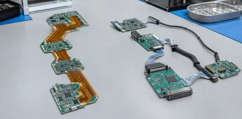
Removing connectors can reduce mating and cable-related failure opportunities, but rigid-flex is not automatically the more reliable architecture. Reliability follows the actual vibration, bend, installation, thermal and service conditions plus the quality of the specialized construction.
Put failures in the right architecture
For a single large rigid board, review unsupported-board strain, mount and enclosure alignment, and the connectors actually fitted to the product. Add cable damage or internal connector fretting only when that evaluated architecture contains those interfaces. Rigid-flex adds over-bending, transition stress, copper fatigue, coverlay and service-handling risks. Build the failure-mode table from the actual product configurations and environment.
For high vibration or sealed products, removing accessible connectors may be valuable. For serviceable industrial equipment, replaceable cable or board modules may reduce repair scope. A field technician who must replace an entire integrated rigid-flex assembly can turn one local failure into a larger service cost.
Define bend and service cycles separately
A static installation bend may occur once or a few times; a dynamic hinge or wearable can cycle continuously. Record assembly bends, service bends and operating bends as separate requirements. Protect the flex during installation with fixtures, markings or a defined folding sequence.
At the contextual decision point, send both architecture models, interface list and service assumptions through the QueenEMS rigid-flex/large-board DFM review. The return should identify fabrication, assembly and test questions for each option; product reliability approval remains with the design owner.
Reliability boundary: Eliminate a connector only when the new flex transition and service method have defined qualification evidence.
Model total system cost without multipliers
Compare cost at the complete-system level and avoid unsupported statements that rigid-flex always costs a fixed multiple. Construction, layer count, panel utilization, bend zones, materials, quantity and tooling can change the result substantially.
| Cost element | Large rigid PCB model | Rigid-flex model |
|---|---|---|
| Bare board | Large panel utilization and route | Specialized materials, lamination and panel |
| Interconnect BOM | Connectors/cables only if required | Often reduced, but not always eliminated |
| Assembly labor | Large-board handling and connector fit | Carrier, forming and integrated handling |
| Tooling | Large stencil/carrier/test fixture | Flex support, forming and test fixtures |
| Inspection | Large-area dimensional/flatness evidence | Transition, flex and formed-shape evidence |
| Rework | Access across one broad board | Integrated assembly may be harder to isolate |
| Service | One large module or connected modules | Whole integrated assembly or designed replaceable unit |
Quote prototype and expected production quantities. NRE can dominate early rigid-flex builds, while connector and labor savings may matter more later. Include redesign likelihood: a changing interface is easier to revise on separate rigid modules than inside an integrated stack.
The large PCB manufacturing cost model helps expose panel, tooling and handling assumptions for the rigid option. Ask the rigid-flex quote to expose its own panel and tooling assumptions rather than comparing only unit prices.
Cost rule: Choose from two comparable bills of process and service, not a bare-board price ratio.

Choose by product and revision stage
The best architecture can change as the product matures. A prototype with uncertain connector pinout, enclosure geometry or sensor position may benefit from rigid modules and replaceable cables. This makes revisions visible and avoids retooling an integrated rigid-flex construction for every change.
Once the geometry and interfaces stabilize, rigid-flex may reduce assembly steps and volume in a product that must fold through a fixed path. A large rigid PCB may remain preferable for a planar industrial panel, LED/control assembly or backplane where chassis support is already designed and service access matters.
Supplier strategy also changes with architecture maturity. A large rigid prototype may be available from more approved sources, while a demanding rigid-flex stack narrows the qualified route and makes early fabrication feedback more valuable. Record alternate material and construction approval boundaries before the design is locked to a single interpretation.
Configuration control is especially significant when rigid sections carry different functional revisions. An integrated rigid-flex assembly ties those sections to one fabrication revision; modular rigid boards can sometimes change independently. Include expected change frequency in the architecture review rather than treating revision management as an administrative detail.
Use three decision scenarios:
| Product geometry | Architecture starting point |
|---|---|
| Flat, accessible enclosure | Prefer the large rigid baseline and prove support/equipment fit |
| Several fixed planes with constrained space | Compare rigid-flex against rigid modules plus cables/connectors |
| Repeated product motion | Start from dynamic-flex requirements; reject unsupported rigid boards and unqualified static bends |
Freeze the architecture before detailed routing only when the enclosure, load path, bend state, interfaces and service strategy are mature enough to support it.
Prepare a comparable RFQ
Send the same functional requirements for both candidates so quotes remain comparable.
| Comparison input | Required content for both candidates |
|---|---|
| Product geometry | 3D STEP model in installed and manufacturing states |
| Interfaces | Functional block map and connector alternatives |
| Circuit construction | Proposed stack-up plus Gerber/ODB++, drill, drawings, BOM and centroid/CPL |
| Mechanical behavior | Bend regions, directions, radii, cycle classification and rigid-board support |
| Production route | Controlled impedance, high current, panel/carrier and test-state expectations |
| Commercial lifecycle | Prototype/production quantities, revision outlook and service strategy |
Ask QueenEMS to review both concepts against the large format PCB manufacturing route. The engineering team can return fabrication and assembly questions, identify which assumptions differ and prepare separate quotation routes without promising a universal winner. To begin the comparison, send the rigid and rigid-flex data packages and request that board, tooling, assembly and test scope be itemized.

Record the architecture release decision
Keep the comparison as a controlled engineering record rather than a meeting conclusion. Capture the evaluated revisions, assumed volumes, connector count, support method, bend state, assembly route, test approach, service model and unresolved risks. When the enclosure or interface changes, the team can see whether the original decision still applies instead of repeating the debate from memory.
Decision point: Approve the architecture only when geometry, electrical transitions, production route, qualification and service are compared on the same revision.
FAQ
Is rigid-flex always more reliable than one large rigid PCB?
No. Rigid-flex can remove connector interfaces that exist in the compared baseline, but adds bend and transition risks. Reliability depends on installation, motion, vibration, temperature, support and qualification evidence for the chosen structure.
Is a large rigid PCB always cheaper?
The bare board is often simpler, but total product cost can include connectors, cables, chassis support, assembly and service. Compare the complete route at prototype and production quantities.
Can rigid-flex carry high-speed signals between rigid sections?
Yes when the flex stack-up, reference path, transition geometry and bend are designed and manufactured for the channel. Model the complete path and require supplier-approved construction before release.
Which option is easier to repair?
A modular rigid system is usually easier to replace by section. One large rigid board and integrated rigid-flex can both enlarge the replacement unit unless the product deliberately provides service partitions.
What should the first prototype prove?
Prove installed geometry, assembly/forming sequence, connector or transition behavior, test access, mechanical support, electrical performance and safe removal before optimizing unit cost.
Sources
- Altium comparison of flex, rigid-flex and rigid PCB tradeoffs
- Altium rigid-flex design documentation: regions, bending and installed geometry
Written by the QueenEMS Engineering Team
Upload your files today · Free DFM check before production · Ship worldwide
Get your PCB prototypes in as fast as 24 hours. We handle FR4, Rogers, and hybrid boards up to 40 layers in volume production, with advanced builds subject to engineering review — free prototypes for 2–4 layer FR-4 boards, no minimum order.
Just upload your Gerber + BOM — we source every part, assemble, and inspect (AOI + X‑Ray) so you don't have to chase suppliers. Boards ship in as fast as 24 hours.