
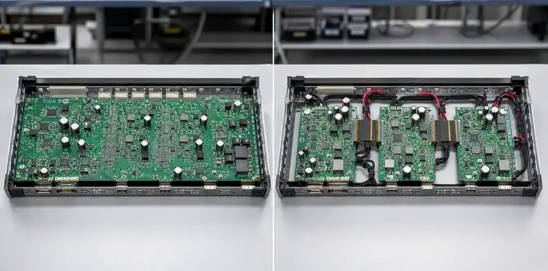
Quick Answer: One large PCB costs less only when the saved connectors, cables, assembly steps and integration work outweigh the board’s lower panel utilization, handling risk and replacement cost. Multiple smaller boards usually improve modularity, supplier choice and serviceability, but they add interconnects, mechanical interfaces and separate test operations. Compare total system cost at prototype and production quantities instead of comparing bare-board area alone.
Comparing one large PCB vs multiple boards is an architecture decision disguised as a board-price question. The bare-board quote matters, but it is only one line in a system that also pays for connectors, harnesses, assembly labor, test, enclosure features, inventory and field replacement.
A single board can remove many interfaces and keep signal paths continuous. A modular design can contain failures, simplify revisions and fit standard fabrication or assembly equipment. The lower-cost choice changes with volume, mechanical layout, channel speed, power distribution and how the product will be repaired.
Table of Contents
- Start with the product architecture
- Compare panel economics for one large PCB vs multiple boards
- Price every interconnect in a split design
- Account for assembly and test operations
- Model yield, rework and replacement exposure
- Protect signal, power and mechanical behavior
- Use volume and revision stage to decide
- Create a comparable quotation model
- Revisit the architecture when the product changes
Start with the product architecture
The first decision is whether the functions truly need one continuous physical platform. Cost analysis comes after identifying interfaces that may be split safely and interfaces whose electrical or mechanical behavior would become worse.
Map the product into functional zones: power conversion, processing, communications, sensors, user interface, connectors, test access and replaceable wear areas. Draw every signal, power rail and mechanical relationship that would cross a proposed board boundary. A split that looks easy in the schematic may require a high-pin-count connector, controlled-impedance transition, shielding, additional ground contacts or a service loop in the enclosure.
One large board is attractive when component spacing is fixed across a wide surface, as in LED arrays, test interfaces or distributed connectors. It can also simplify systems where hundreds of nets would otherwise cross a backplane or harness. Multiple boards are attractive when modules sit at different angles, need independent replacement, change on different revision cycles or can use existing cable interfaces.
Do not let an online prototype price determine the architecture. Low-cost pooled services reward small standard outlines in a way that may not represent production. Conversely, a custom large-board quote may appear expensive while removing several connectors and assembly operations.
The large format PCB manufacturing page establishes whether the continuous outline is feasible. The architecture review determines whether preserving that outline is worth the system consequences.
Compare panel economics for one large PCB vs multiple boards
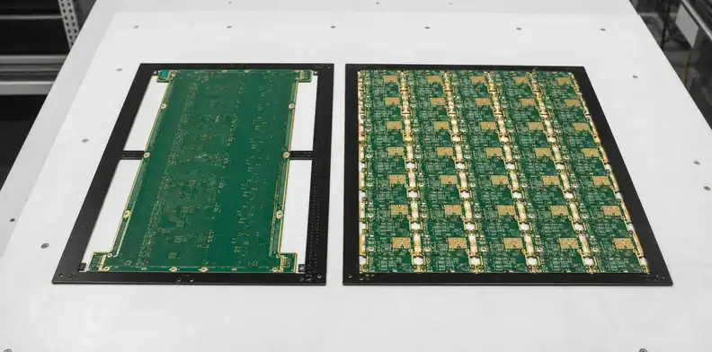
Board cost is driven by production-panel use and process route, not simply by the sum of finished-board areas. A large outline can consume a dedicated panel and leave material that cannot carry another product.
For each option, ask the fabricator to show or describe the assumed production format. A single large board may run one-up. Smaller modules may nest several-up, share tooling margins and produce more sellable units from the same material. Odd shapes, long narrow outlines and large internal cutouts can reduce utilization even when the calculated square area looks reasonable.
Layer count can reverse the answer. Splitting a crowded board may allow one module to remain multilayer while another uses a simpler construction. The opposite can also happen: duplicated power and ground structures, extra connector escape routing and separate mechanical margins can increase the total layer-area cost.
Include these fabrication terms in the comparison:
- laminate and copper area consumed by the production panel;
- number of finished boards per panel;
- layer count and lamination cycles for each module;
- drilling, routing and edge-feature complexity;
- electrical test route and any fixture cost;
- tooling, setup and minimum order conditions;
- protected packaging for one large board or several modules.
| Cost line | One continuous board | Several modules |
|---|---|---|
| Production panel | Often one-up with dedicated margins | Better nesting may be possible |
| Layer construction | One shared stack across all functions | Each module may use a different stack |
| Tooling and setup | Fewer jobs but possible special handling | More jobs using standard fields |
| Packaging | Large protected format | Multiple smaller packs and labels |
The PCB panel cost article explains why usable output per panel matters. For a large-board decision, request the cost model at the actual quantities rather than extrapolating a prototype calculator.
Cost signal: Compare sellable output per qualified panel at the intended quantity instead of comparing finished board area alone.
Price every interconnect in a split design
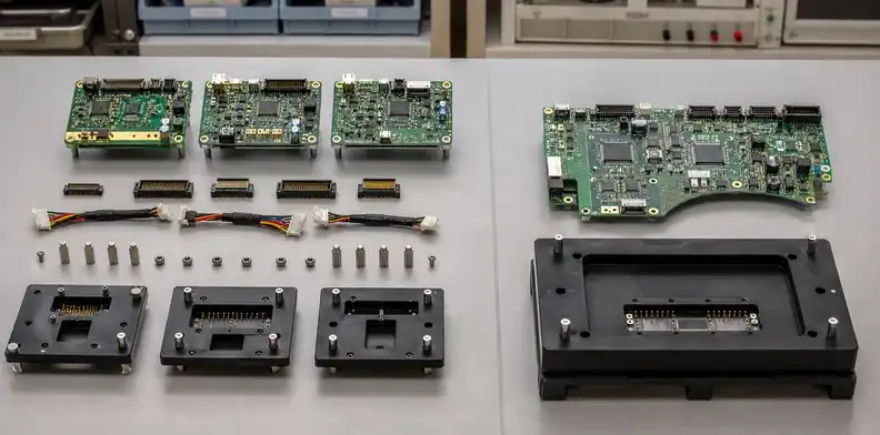
A modular architecture adds more than the visible connector price. Count both mating halves, cable or flex, contacts, hardware, board area, sourcing risk, assembly and inspection.
Create an interconnect bill for each proposed split. Include headers, receptacles, harnesses, latches, strain relief, shielding, keying and mounting hardware. Add the PCB area needed for connector footprints and escape routing. If high-current rails cross the boundary, include contact derating and voltage-drop consequences. High-speed links may need more ground pins, matched connector geometry and simulation or test work.
Keep the costing model connected to the system design. Altium’s multi-board documentation distinguishes child-board data from system-level connectivity and the aggregated BOM. Reconcile the mating parts and cables against that system record before treating the modular quotation as complete.
Connector availability can become a lifecycle issue. A single-board design may have a higher fabrication risk but fewer purchased interconnects. A modular system can use replaceable boards yet become dependent on a specialized connector with a long lead time or limited alternatives. The architecture team should decide whether that supply risk is acceptable before layout locks the footprint.
Cable assembly is another cost center. A harness needs drawings, parts, crimp tooling, continuity test, labeling and installation. Incorrect routing or insufficient strain relief can create failures that do not exist on a continuous PCB. Rigid-flex can remove discrete connectors in some products, but it introduces a different fabrication and test structure rather than a free connection.
Use a separate line for engineering validation. New interconnects can require signal-integrity review, EMC testing, mating-cycle validation and mechanical tolerance work. Those costs are easy to omit from a spreadsheet because they do not appear in the first PCB quote.
Account for assembly and test operations
More boards usually mean more handling, programming, inspection and final connections, while one oversized board may require a specialized assembly route. Compare the complete process flow rather than SMT placement count alone.
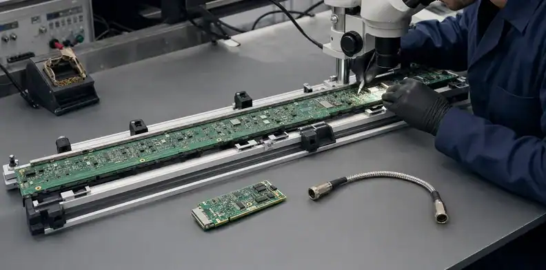
For one large assembly, confirm stencil, placement, conveyor, reflow, AOI and test fields. The board may need a carrier or additional support. For multiple boards, each module needs its own paste print, placement program, reflow pass, inspection identity and handling. Final product assembly then adds board installation and interconnect mating.
Testing can favor modularity. A failed module can be isolated and replaced before system integration. Smaller fixtures may be less expensive and easier to maintain. One large board can simplify boundary-scan or functional routing when the full system is present, but a failure may require troubleshooting across a larger, higher-value assembly.
Create a route table:
| Operation | One large PCB | Multiple boards |
|---|---|---|
| SMT setup | One job, possibly special equipment | Several jobs, often standard equipment |
| Inspection | Wide field and support challenge | Repeated standard inspections |
| Programming | One integrated target or several devices | Module-by-module control possible |
| Functional test | Full system available early | Module fixtures plus final system test |
| Final assembly | Fewer inter-board connections | More mating and cable-routing steps |
The PCB assembly test strategy can help assign coverage. The architecture comparison should state which faults are caught at module level and which require the assembled product.
Integration call: Count every setup, inspection, programming step and final system test before calling the modular option cheaper.
Model yield, rework and replacement exposure
A defect on one large board places more accumulated value at risk, while modular designs contain loss but add more opportunities for interconnect and handling defects. Yield must be evaluated at both board and product level.
Suppose one assembly combines a high-density processor, power stage and wide connector field. A fabrication defect or damaged connector can scrap or rework the whole board. If the same product uses three modules, a failure may be limited to one module. The modular option still needs three good boards and reliable connections, so its system yield is not simply the best individual-module yield.
Consider component value as well as PCB value. A large populated board can carry expensive devices before a late functional fault is found. A staged module test may prevent those parts from entering final integration. On the other hand, duplicating regulators, connectors or protection circuits across modules may raise material cost and create more solder joints.
Field service is often decisive. Replacing one accessible module can reduce repair cost and preserve the rest of the product. A monolithic board can reduce field connections but may force replacement of a much larger assembly. Products with sealed enclosures or no field service may value fewer interfaces more highly than modular repair.
Record the expected rework method. Large boards require enough support during manual repair; heating one region can create stress elsewhere. Smaller boards are easier to handle but connectors can be damaged during repeated service. The PCB prototype-to-production decision process helps ensure that a repairable prototype architecture is reassessed before volume release.
Protect signal, power and mechanical behavior
The lower-cost option must still preserve channel performance, power integrity and mechanical alignment. A split creates discontinuities; a large board creates long routes and larger dimensional relationships.
For high-speed signals, list every interface that crosses a connector or cable. Review impedance, return-path continuity, reference changes, skew, insertion loss and test access. A single large PCB removes connector transitions but may lengthen traces enough to increase loss or delay. Use the controlled-impedance requirement process for channels whose stack-up and geometry must be quoted.
For power, compare copper loss on a long continuous distribution path with connector contact resistance and harness voltage drop. A modular product may place conversion close to each load. A single board may use broad planes or heavy copper but increase warpage and etching constraints.
Mechanical fit needs a tolerance chain for both options. One board must align widely separated connectors, holes and enclosure features. Multiple boards need brackets, cable length, connector float and independent mounting datums. The right architecture may use slots or compliant connectors to avoid forcing a rigid board into the enclosure.
EMC behavior can also change. A board split may create larger current loops or cable antennas. A continuous board may offer a better reference plane but create a large radiating structure if return paths are poorly controlled. These effects require design review; they cannot be priced accurately from dimensions alone.
Engineering check: Reject a cheaper partition if its interconnect changes exceed the available signal, power, EMC or mechanical margin.
Use volume and revision stage to decide
The best architecture can differ between early prototypes and stable production. Prototype flexibility favors replaceable modules, while mature volume can justify integration that removes recurring interconnect cost.
At concept stage, modules let teams test functions independently and revise one area without rebuilding everything. Off-the-shelf cables and connectors may be acceptable even when their unit cost is high. Before production, revisit the split: stable interfaces may be integrated, or the service benefit may justify keeping modules.
Quantity changes panel utilization, setup allocation, fixture economics and component pricing. Request at least prototype, pilot and expected production breaks. A one-up large panel may carry similar setup effort across quantities, while module panels can improve utilization at volume. Assembly fixtures for multiple modules may become economical only after the production forecast is credible.
Revision cadence matters. If the power module changes slowly but the processor changes annually, separating them can prevent unnecessary redesign and requalification. If all functions change together and the interconnect is expensive, one board may be simpler.
A useful contextual review sends the system block diagram, mechanical envelope, expected quantities and proposed split boundaries. The returned decision should identify cost drivers, critical interconnects and which assumptions need supplier quotations before architecture freeze.
Create a comparable quotation model
Compare one product delivered and tested, not one square centimeter of laminate. Put both architectures into the same cost and risk table.
Use these categories:
- Bare-board fabrication and panel utilization.
- Connectors, harnesses, hardware and duplicated circuitry.
- SMT/THT setup, placement and inspection.
- Module and system-level test fixtures.
- Final assembly labor and mating operations.
- Expected scrap, rework and field replacement exposure.
- Engineering validation for signal, EMC and mechanical fit.
- Packaging, inventory and revision control.
Mark every estimate as quoted, calculated or open. Do not hide an uncertain connector or fixture behind a zero. Compare the same quantities and delivery scope, and keep assumptions beside the totals.
Illustrative break-even example: let the integrated option require $4,000 of setup and $70 per tested product, while the modular option requires $1,000 of setup and $85 per tested product, including its interconnects and final integration. Their modeled totals are equal at 200 products: ($4,000 − $1,000)/($85 − $70). These assumed values exclude service costs. Recalculate with matched supplier scope and an agreed service allowance; the crossover has no decision value until both architectures meet the electrical and mechanical requirements. Revisit the assumptions when the expected repair cost or revision schedule changes.
The model should also assign costs to ownership boundaries. With one board, one supplier can often deliver one tested PCBA, but the physical format may reduce the number of qualified sources. With several boards, sourcing can be divided by technology, although someone must own cable procurement, mating validation, firmware compatibility and final system test. Those tasks do not disappear because they sit outside the PCB quotation.
Before architecture freeze, run one mechanical and electrical prototype of the preferred option and preserve the rejected option’s cost model. Measure connector insertion effort, voltage drop, communication margin, assembly time and service access. If the test exposes a bad assumption, update the model rather than defending the original choice. The objective is a repeatable product-level decision, not proof that one architecture is universally cheaper.
To compare both architectures on the same scope, send QueenEMS both candidate outlines, layer counts, materials, quantity breaks and the system interconnect concept. Keep unresolved DFM assumptions visible; the returned review can quote the fabricable options and identify where a large continuous board, several modules or a revised partition needs further engineering work.
Bottom line: Quote both architectures on identical requirements and select the lower total system cost at the current revision stage.

Revisit the architecture when the product changes
An architecture decision is valid for a defined revision, quantity range and service model. Reopen it when a connector family changes, a module gains high-speed channels, expected volume moves materially, field replacement becomes important or the continuous board crosses a supplier process boundary.
Keep the comparison model with the product record. Updating panel utilization, connector count, fixture scope and replacement exposure is faster and more reliable than repeating the debate from memory. The review trigger also prevents a prototype-driven partition from surviving into production after its original assumptions disappear.
Record rule: Recalculate both architectures whenever the revision changes a major interconnect, process route, production volume or repair strategy.
FAQ
Is one large PCB always more expensive?
No. Its bare-board price may be higher while total product cost is lower because connectors, cables and repeated assembly steps disappear.
Do multiple boards always improve yield?
No. They can contain the cost of one failed module, but the finished product still requires every module and interconnect to pass.
Is rigid-flex a cheaper alternative to one large board?
Not automatically. Rigid-flex can reduce connectors and fit three-dimensional enclosures, but it adds a specialized stack-up, fabrication route and inspection plan.
Which option is better for field repair?
Multiple replaceable modules usually simplify field repair, provided connectors are accessible, keyed and rated for the service environment.
What should I send for a comparison quote?
Send both board concepts, layer/material requirements, quantity breaks, system block diagram, connector plan, assembly scope and test expectations.
Sources
- Siemens Xpedition BluePrint-PCB documentation
- Electrical Engineering Stack Exchange: one big PCB or smaller boards
Written by the QueenEMS Engineering Team
Upload your files today · Free DFM check before production · Ship worldwide
Get your PCB prototypes in as fast as 24 hours. We handle FR4, Rogers, and hybrid boards up to 40 layers in volume production, with advanced builds subject to engineering review — free prototypes for 2–4 layer FR-4 boards, no minimum order.
Just upload your Gerber + BOM — we source every part, assemble, and inspect (AOI + X‑Ray) so you don't have to chase suppliers. Boards ship in as fast as 24 hours.