
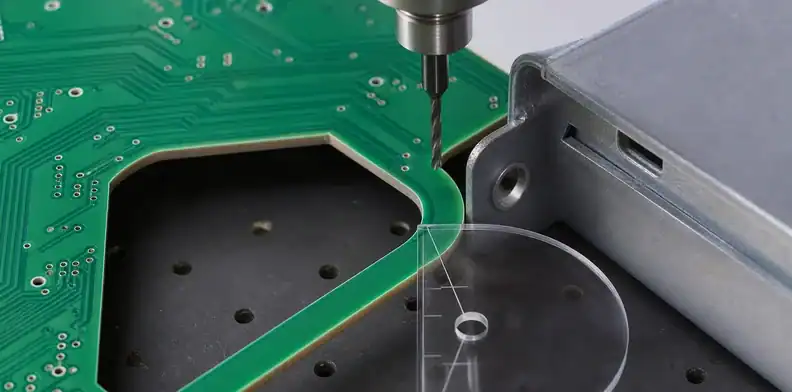
Quick Answer: A routed PCB cannot produce a mathematically sharp inside corner because the cutter has a radius. Set the required internal corner radius from the mating geometry, confirm the usable router tool with the fabricator, and show copper, component, and controlled-depth constraints in the drawing. Do not wait for CAM to round a critical cutout silently.
Key takeaways
- Inside-corner geometry is determined by the cutting process.
- A fit-critical cutout needs a radius requirement, not a rectangular outline alone.
- Small tools, relief features, and controlled-depth routing have different costs and risks.
A sharp corner on a CAD outline often looks harmless until a housing tab, shield, or connector must enter it. CNC routing leaves a radius equal to the cutter path. If that radius is not part of the released mechanical definition, the fabricator must either choose one, request a change, or return a board that fits less well than the design implied.
Table of Contents
- Start with cutter geometry
- Find corners that actually control fit
- Choose a workable radius
- Protect local copper and parts
- Distinguish routing from depth control
- Review CAM alternatives deliberately
- Inspect the cutout against the mating use
- Send the right RFQ inputs
- Use a routed-corner review to avoid enclosure rework
- Choose a routing relief before specifying a tiny cutter
Start with cutter geometry
The internal radius comes from the router tool, not from a drawing preference. Smaller tools can reach tighter geometry but may change cost, panel strategy, edge finish, and processing margin. Confirm the relevant capability for the material and board thickness rather than copying a nominal radius from another supplier.
A router bit creates an inside radius because its centerline cannot reach a mathematical corner. The usable minimum depends on tool diameter, laminate construction, overall thickness, panel rigidity, and feature depth. A small cutter may create the radius a housing requires, but it can slow routing and be less tolerant of demanding material or copper distribution. Confirm the route with the fabricator that will build the job.
Tool rule: An inside corner must be compatible with the cutter path, not just the CAD outline.
Find corners that actually control fit
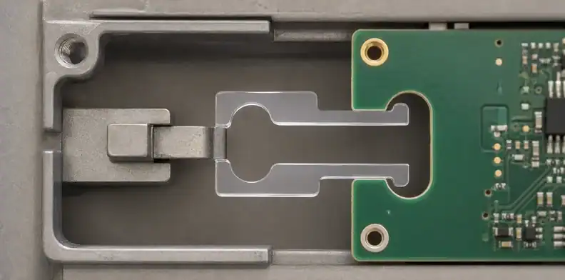
Card guides, enclosure keys, shielding features, board-to-board clearances, and fixture openings need deliberate review. A noncritical cosmetic cutout can accept a normal radius. A corner that locates a connector or allows a latch to pass should be called out against its mating part.
Examine the mating feature in motion, not just as a static outline. A shield tab may enter at an angle, a latch may sweep through a corner, and a connector housing may have mold radii that are not visible in the nominal CAD silhouette. The cutout can often use a normal radius when clearance exists; reserve special geometry for the few corners that actually control assembly.
Geometry rule: Use a designed relief where a mating tab cannot accept a normal router radius.
Choose a workable radius
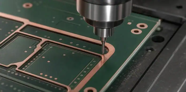
Set the radius from the mechanical clearance and show it on the fabrication drawing. When the mating part needs a square visual envelope, a relief notch or dog-bone feature may create the required clearance without demanding an impossible cutter path.
A dog-bone or relief feature is sometimes a better solution than a very small cutter. It creates local clearance for a square mating tab while leaving the bulk of the cutout easy to route. The drawing should show its radius and center location clearly. Avoid hiding it as an accidental polygon detail, because an outline cleanup or panelization edit can remove the very feature the mechanical designer depended on.
| Situation | Preferred treatment | Drawing fields that matter |
|---|---|---|
| Enclosure tab | Radius from mating clearance | Section view and first-article fit |
| Shield opening | Local cutout radius | Copper and component keepout |
| Flex relief | Material-specific bend geometry | Rigid-flex stackup and bend area |
| Depth pocket | Pocket radius and remaining thickness | Controlled-depth drawing |
Protect local copper and parts
Routing moves through laminate near copper pours, pads, vias, components, and inner layers. Preserve an explicit keepout around the cut path and check that a later outline change cannot erase it. The mechanical fit is not acceptable if it creates exposed copper or damages a nearby pad.
Copper needs clearance around the true cutter envelope, including the round end of the path. A polygon pour may appear outside a rectangular cutout but still be too close to the routed corner radius. Check outer and inner layers, via fences, test pads, and component overhang. In a high-current area, also ask whether the new void changes a return path or creates an unacceptable narrow neck.
Keepout rule: Review the circular cutter envelope, not only the nominal rectangular opening.
Distinguish routing from depth control
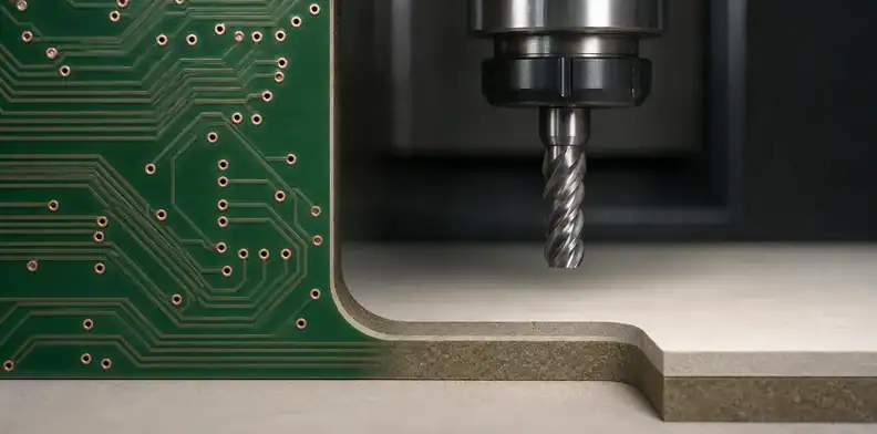
A through cutout, an outline route, and a controlled-depth pocket use different process assumptions. State which face is machined, the remaining thickness where relevant, and whether the corner requirement applies to the full board thickness or a local pocket.
A through cutout and a controlled-depth pocket deserve separate notes. A pocket may have a different corner radius at its floor, a remaining dielectric requirement, and a controlled entry side. Do not use an outline dimension to imply pocket depth or assume that the same tool will be available for both operations. A section view removes uncertainty about the final three-dimensional shape.
The linked PCB outline tolerance requirements material explains edge workmanship; it does not replace the radius and toolpath definition for an internal cutout.
Review CAM alternatives deliberately
CAM may suggest a larger radius, a different tab arrangement, a smaller tool, or a relief change. Engineering should compare that proposal with the actual enclosure geometry. Treat the response as a mechanical deviation decision, not as a generic production optimization.
When CAM proposes a larger radius, compare it against the actual interfering geometry. Engineering may accept it, add a relief, shift a nearby tab, or specify a smaller tool if the cost and process risk are justified. Routing staff should not quietly round a fit-critical corner simply because the file contained a sharp vertex. The deviation must be visible in the released manufacturing record.
| Routed-corner check | Evidence | Decision owner |
|---|---|---|
| Required internal radius | Profile drawing with callout | Mechanical designer |
| Tool access | Fabricator routing assessment | CAM engineering |
| Copper exclusion | Layer-by-layer keepout review | PCB layout owner |
| Mating clearance | Housing or fixture trial | Product validation |
Pocket rule: A controlled-depth feature needs its own section and acceptance dimensions.
Inspect the cutout against the mating use
Measure the radius and key dimensions on the first article, then test the board with the released mating feature when practical. A caliper can confirm a gross size but may not prove that a tab clears through the entire insertion path.
Inspect the first article with the housing, clip, or gasket that motivates the cutout. A caliper confirms span but cannot show whether a tab binds halfway through insertion. For an inaccessible finished assembly, make a go/no-go gauge that reflects the worst-case mating corner. Record the used radius and the revision of the gauge so later boards are checked against the same mechanical intent.
Use controlled-depth routing requirements to verify surrounding profile dimensions after the inside-corner geometry has been finalized.
Send the right RFQ inputs
Provide the outline layer, mechanical drawing, mating CAD section, radius and keepout callouts, stackup if depth routing is involved, and any fit sample. QueenEMS can separate normal routing from a feature that needs a controlled manufacturing response before quotation.
The RFQ needs a profile drawing, local section views for pockets, thickness, requested internal radii, relevant copper keepouts, and the mating model or controlled dimensions. State whether tabs, rails, or panel breakouts are restricted near the feature. With that input, the fabricator can assess tool access before material is committed rather than discovering a contradictory corner during final routing.
Assembly rule: Verify the corner against the actual mating part or an equivalent gauge.
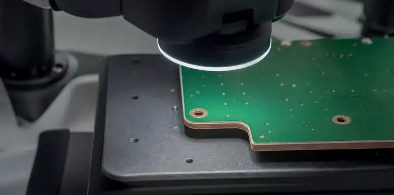
Use a routed-corner review to avoid enclosure rework
A metal enclosure may show a square tab in its CAD model, but the manufactured tab usually has its own bend radius, burr condition, and insertion path. Overlay that real interface with the proposed PCB cutout before selecting a router radius. If the tab needs clearance only at two corners, a localized relief can be safer than shrinking the cutter for the entire panel. The layout should identify the relief as intentional mechanical geometry and maintain copper clearance around its circular toolpath. This avoids the opposite problem of adding an expensive tiny-radius route that solves a theoretical CAD conflict while creating fragile routing conditions for every production board.
Controlled-depth routing requires particular care because the visible outline can hide a three-dimensional conflict. A pocket may be intended to accept a battery, a shield wall, or a mechanical latch while leaving a specified dielectric floor. The corner radius at the bottom of that pocket may differ from the top opening, and nearby buried copper can be closer than it appears in a top-layer view. A section drawing should state the entry face, pocket depth, remaining thickness, and radius requirement. It should also show whether the mating part bears on the pocket floor or merely passes through the opening, since those functions lead to different acceptance checks.
For first-article evaluation, use the actual housing or a gauge that reproduces the critical tab geometry. Slide or seat the board through the full mechanical motion and inspect the edge for stress whitening, fiber pull-out, or contact with copper. If CAM offers a radius change, test that proposal against the same gauge before approving it. Recording the trial as a mechanical fit result makes it possible to repeat a successful route on later revisions even when the panel layout, board thickness, or routing supplier changes.
Before fabrication, review each critical opening as a route that has a tool diameter and an approach path. Mark which inside corners are cosmetic, which clear a static part, and which allow a latch, guide, shield, or cable feature to move during assembly. For the functional corners, provide a radius or relief geometry that can be checked in the mechanical drawing. Add a complete copper and component keepout around the actual cutter envelope, including all layers for a through route. Where the feature is a pocket, include a section showing its entry side, depth, floor thickness, and the radius expected at the floor. This separates a simple outline route from a controlled-depth operation and prevents a quotation from combining them under one vague cutout note. The proposed inspection should match the risk: a caliper may be enough for a clearance slot, whereas a released housing or go/no-go fixture is better for a keyed opening. If a fabricator asks for a larger radius, retain both the proposed radius and the mating decision in the revision record. That trace keeps a later enclosure update from unknowingly depending on a corner shape that was never approved for production.
Routing geometry should be reviewed with manufacturing realism. A cutout that leaves narrow webs, loose islands, or a weak panel edge may be hard to hold even if a nominal small tool exists. Board thickness, material type, copper balance, and breakout strategy influence the route. When the design needs a small internal radius, request a fabrication assessment that names the proposed tool and any limitation. When the route is merely cosmetic, allow a standard radius and keep the drawing simple. This distinction protects the scarce tight-corner capability for assemblies that genuinely need it and prevents later panel changes from compromising a corner whose mechanical function was never documented.
Choose a routing relief before specifying a tiny cutter
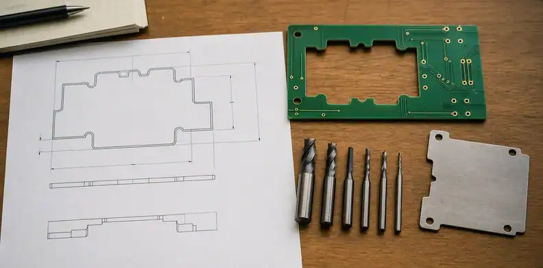
A square mating tab does not automatically require the smallest available router tool. Compare a dog-bone, a local circular relief, a shifted tab, and a smaller cutter against the real clearance envelope. The selected geometry should be dimensioned as an intentional design feature and should preserve enough laminate around the cutout for panel handling. This decision often reduces fabrication risk while protecting the fit that the original sharp CAD corner was intended to provide.
Relief rule: Prefer a documented clearance feature when it protects fit more reliably than an unnecessarily small routing tool.
FAQ
Can a routed PCB have a sharp internal corner?
No. A routed path leaves a radius; use an approved relief geometry when a mating part needs local clearance.
Is the smallest router always best?
No. It may add cost or reduce process margin without improving the functional fit.
Does the board outline define the radius?
Only when the CAD geometry and the drawing explicitly make the required radius clear.
What should be checked on the first article?
Check the radius, local keepouts, and fit with the actual mating part or a controlled gauge.
Review a fit-critical routed cutout
Send the profile drawing, pocket sections where applicable, local keepout layers, board thickness, and mating model to QueenEMS. The fabrication discussion can then resolve tool access before the cutout reaches production routing.
Sources
Written by the QueenEMS Engineering Team
Upload your files today · Free DFM check before production · Ship worldwide
Get your PCB prototypes in as fast as 24 hours. We handle FR4, Rogers, and hybrid boards up to 40 layers in volume production, with advanced builds subject to engineering review — free prototypes for 2–4 layer FR-4 boards, no minimum order.
Just upload your Gerber + BOM — we source every part, assemble, and inspect (AOI + X‑Ray) so you don't have to chase suppliers. Boards ship in as fast as 24 hours.