

Quick Answer: PCB Dk and Df values are comparable only when the material condition, test method, and frequency are identified. A lower number on one datasheet is not automatically a lower-loss or lower-impedance-risk construction than another supplier’s value. For a high-speed RFQ, compare named test conditions first, then require the fabricator to connect the approved laminate and pressed stack-up to the impedance or channel evidence used for release.
PCB Dk and Df test methods create a quiet source of procurement error. A buyer receives two material tables, compares the lowest Dk or Df entry, and assumes the values describe the same condition. Often they do not. One figure may be based on a different frequency, test fixture, resin content, direction, or laminate construction. The numbers can both be legitimate and still be unsuitable for a direct winner-loser comparison.
Start the comparison by keeping the method, frequency, construction, and material revision beside each value. The material-family selection page covers application fit; this article addresses the evidence needed before one Dk/Df table is allowed to drive a real high-speed stack-up.
Table of Contents
- Why Dk and Df entries can disagree without either supplier being wrong
- Which fields make two material values comparable
- How Dk affects impedance decisions
- How Df relates to channel loss
- What not to infer from a datasheet table
- How to compare alternatives during quoting
- What evidence should close the release decision
Why Dk and Df entries can disagree without either supplier being wrong
Dk and Df are measured properties, not fixed labels printed permanently on a laminate family. The result depends on how the sample is prepared and measured. Frequency is one major variable: a value reported near a low-frequency condition may not represent behavior in a much faster digital or RF channel. Test method is another variable because methods sample electric fields and material constructions differently.
The construction also matters. A resin-rich prepreg, a glass-reinforced core, and a pressed dielectric from the same product family can have different effective properties. Direction may matter for anisotropic constructions. A raw material coupon may therefore be useful for material comparison but insufficient for predicting the exact electrical behavior of a finished multilayer board.
The safe reading is not that datasheets are unreliable. It is that a value needs its label. IPC technical material on high-frequency Dk and Df methods shows that differing methods and frequencies can produce differing reported values. That is why a procurement comparison should preserve the test-condition column rather than stripping it out to make a simpler price table.
Comparison rule: Do not rank materials by Dk or Df until the two values have the same stated context or the difference has been explained by the supplier.
Which fields make two material values comparable
Ask suppliers to provide a complete comparison row, not a marketing excerpt. The row should include material name and revision, construction or glass style, nominal resin state, test method, frequency, reported Dk, reported Df, and whether the result applies to core, prepreg, or pressed construction. A missing field is not a minor formatting problem; it is the reason the comparison may be invalid.
| Field | Why the buyer needs it | Common mistake |
|---|---|---|
| Test method | Defines how the property was measured | Comparing unlike method names as one dataset |
| Frequency | Shows where the number applies | Using a low-frequency entry for a high-speed channel claim |
| Material construction | Identifies resin and glass condition | Treating every prepreg style as identical |
| Product revision | Protects repeat-order traceability | Quoting a family name without a controlled revision |
| Pressed dielectric | Connects raw data to the stack-up | Approving a core table for an unqualified prepreg layer |
This format also exposes a useful distinction: design Dk is the value used to calculate approximate geometry, while the effective Dk of the finished build is what matters for final impedance and delay. The fabricator may use a field solver and process knowledge to adjust width or dielectric assumptions. That is acceptable only when the change is visible and the design owner approves the resulting construction.
For material family context, compare the data against the Rogers RO4000 laminate family or the I-Speed low-loss epoxy material article. Do not use either page as a substitute for the actual manufacturer’s current data sheet.
Data check: A value without its test method and frequency remains a screening clue, not an approved electrical input.
How Dk affects impedance decisions
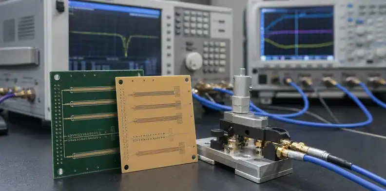
Dk affects the electric field around a conductor and therefore helps determine the trace width, spacing, and dielectric height needed to meet an impedance target. But a material’s reported Dk is not a command to route every trace to a fixed geometry. Finished copper thickness, solder mask, plane spacing, glass/resin distribution, and fabrication press-out all influence the final result.
An impedance calculation should identify the construction it assumes. If a buyer sends a target such as 100-ohm differential impedance but omits the intended dielectric thickness and material, the supplier must either propose a stack-up or make an assumption. The right commercial response is to show that assumption in the quote or CAM question, not to hide it behind a nominal material name.
The controlled-impedance stack-up reference explains the broader relationship between reference planes and layer count. For a material decision, add the Dk test context and the pressed dielectric value to the stack-up approval table.
When a fabricator proposes a material alternative, compare the new effective geometry rather than only comparing two Dk entries. A lower-Dk alternative can require a different trace width, change available BGA escape room, or affect pair spacing. That may be acceptable, but it is a board revision decision.
How Df relates to channel loss
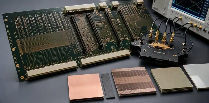
Df is used to describe dielectric loss. In a high-speed channel, dielectric loss is only one part of the insertion-loss picture; conductor roughness, copper profile, trace length, vias, connectors, and discontinuities also contribute. A low Df material can be the right choice for a long or high-frequency path, yet the board may still fail its channel target if the rest of the construction is uncontrolled.
Keep the decision tied to the actual interface. A short connection with large margin may not justify a high-cost low-loss construction. A long backplane path, a high-speed channel with a tight loss budget, or a sensitive RF feed may justify a more rigorous material and coupon review. The point is not to choose the lowest Df on a list; it is to choose a construction that supports the channel budget with traceable evidence.
Copper must be discussed alongside Df. The HVLP copper foil RFQ article covers why foil profile can matter to loss. A material comparison that ignores copper treatment cannot describe the finished transmission line completely.
Loss rule: A Df value is a screening input. Channel acceptance needs the combined laminate, copper, geometry, and measurement boundary.
What not to infer from a datasheet table
Do not infer that a named material family has one Dk, one Df, one impedance response, or one available glass style. Do not infer that two values with the same number of decimal places have the same precision. And do not infer that a supplier can deliver the exact construction used in a laboratory data sheet at the thickness and copper schedule required by the board.
Another mistake is turning a datasheet number into a warranty for system performance. A laminate vendor’s published data supports material selection. It does not validate the customer’s connector model, package breakout, via design, or return-path continuity. Those items should be addressed in the design and qualification plan.
Be careful with generic phrases such as “low loss” and “high speed.” They describe a market category, not a tested construction. A good RFQ replaces them with a named material or permitted alternatives, target frequency or data rate, critical layers, impedance targets, coupon expectation, and approval requirement for substitutions.
For a focused material comparison, the Megtron 8 PCB material review illustrates the kind of project information that should accompany a high-speed material discussion. The material name itself is never the whole release package.
How to compare alternatives during quoting
Ask each supplier to fill the same material-comparison table. Keep price separate from technical fields so a cheaper quote does not obscure an unapproved construction change. If an alternate is offered, ask which layers change, whether trace geometry changes, whether the construction uses a different glass style, and what evidence will be available before production.
The review should have three outcomes. The first is an approved named construction. The second is an acceptable alternate subject to a revised stack-up and design approval. The third is a rejection because the proposed material cannot meet a channel, processing, or availability requirement. This is clearer than leaving a quote with an open note such as “equivalent material may be used.”
For a prototype, the buyer may accept a controlled alternate if it proves routing and assembly. For production, tie the accepted construction to the released drawing and purchase order. The material-change sign-off workflow gives a practical framework for documenting that boundary.
Add an explicit comparison note to the quote review. It can state: “Dk and Df entries are comparable only where the supplier names the method, frequency, and applicable construction. A material alternative must identify the proposed core and prepreg, pressed thickness, and any required geometry change.” That sentence gives purchasing a reason to return a technically incomplete quote without turning the commercial team into laminate specialists.
When several suppliers use different data-sheet formats, normalize the inputs in a project-owned table. Keep original source references and do not round values merely to make the rows look uniform. The table is an engineering decision record, not a marketing comparison. It should show which fields are confirmed, which are supplier assumptions, and which must be verified by a coupon or field-solver result.
| Quote outcome | What must match | Hold point |
|---|---|---|
| Named construction | Method, frequency, construction, and pressed thickness | A value lacks its test condition |
| Proposed alternate | Affected layers and revised line geometry | The alternate changes loss or BGA escape room |
| Prototype exception | Limited build purpose and evidence plan | An exploratory quote is copied into production release |
Release check: Accept a Dk/Df comparison only when the released stack-up names the construction that produced the values being compared.
What evidence should close the release decision
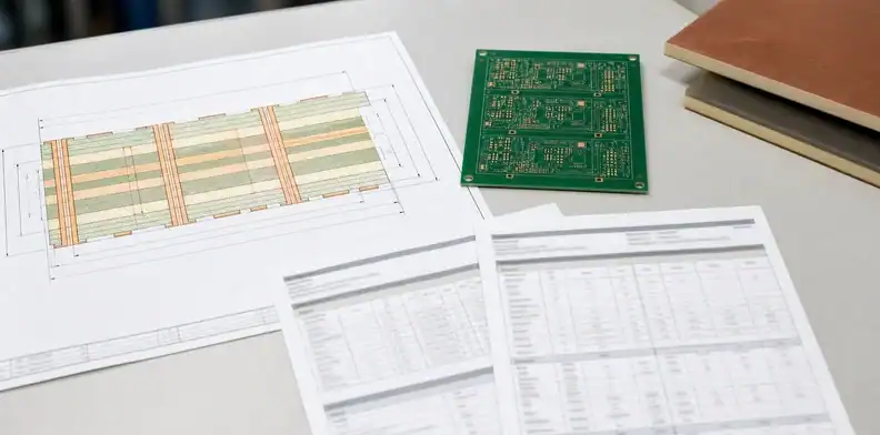
The final evidence package should distinguish supplier material data from board-level evidence. A material data sheet establishes the stated property for a named construction and condition. A controlled stack-up, coupon, or channel measurement establishes how the selected materials were applied to this board. Keeping both prevents either document from being asked to prove more than it can.
Close the decision with a stack-up that names every electrically relevant dielectric, its finished thickness, copper construction, and approval revision. Add the calculation or coupon requirements that correspond to the critical nets. If the board is high risk, preserve the material data sheet revision and the supplier’s substitution statement in the project record.
The evidence should answer a simple question later: what was actually built, and why was it accepted? A generic material family, a screen capture of a datasheet, or a verbal promise cannot answer it reliably on a repeat order. A signed stack-up, CAM response, and defined test evidence can.
For a channel where material risk is high, preserve the calculation inputs as well as the final result. Record the target impedance, layer number, line geometry, copper assumption, dielectric thickness, material construction, and reference-plane condition. A test coupon report becomes much more useful when it can be compared with those inputs rather than being filed as an isolated pass/fail document.
Separate acceptance from investigation. If a prototype measurement differs from the calculation, first determine whether the stack-up, copper condition, or measurement boundary changed. Do not immediately relabel the material as unsuitable. That disciplined comparison is what allows the next build to improve instead of restarting the same argument with a different data sheet.
A clear decision log records the reason a candidate was selected. It may be lower loss at a stated frequency, availability of a required construction, compatibility with a known press cycle, or a better fit for the channel model. Recording the reason helps later engineers decide whether a replacement preserves the original intent.
QueenEMS can review a material comparison when you send candidate data sheets, the planned stack-up, target impedance or frequency, copper preferences, and the interfaces that drive the decision. The output can distinguish a quote-stage assumption from a construction that is ready for approval. Send the package through the QueenEMS contact page.
FAQ
Can I compare Dk values from two different test methods?
Only with a qualification. The values may help shortlist candidates, but they are not a direct apples-to-apples ranking until method, frequency, and material construction have been aligned.
Does a lower Df guarantee lower insertion loss?
No. Df is one contributor to dielectric loss. Copper profile, line geometry, trace length, vias, and connectors can materially change the finished channel result.
Should the RFQ list design Dk or finished impedance?
List both when available. Design Dk helps show the intended material assumption; the impedance target and approved stack-up define the finished electrical requirement.
What is the first document to request from a material supplier?
Request the current datasheet with test conditions. Then connect it to the actual core, prepreg, and pressed construction proposed for the board.
Sources
Written by the QueenEMS Engineering Team
Upload your files today · Free DFM check before production · Ship worldwide
Get your PCB prototypes in as fast as 24 hours. We handle FR4, Rogers, and hybrid boards up to 40 layers in volume production, with advanced builds subject to engineering review — free prototypes for 2–4 layer FR-4 boards, no minimum order.
Just upload your Gerber + BOM — we source every part, assemble, and inspect (AOI + X‑Ray) so you don't have to chase suppliers. Boards ship in as fast as 24 hours.