
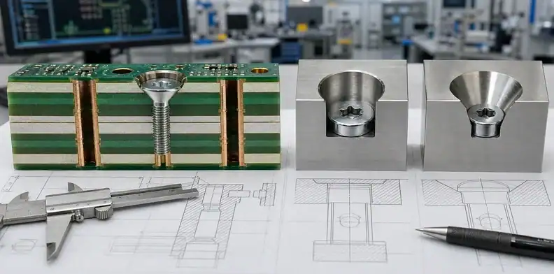
Quick Answer: Choose a counterbore when a fastener needs a flat-bottom recess for a socket-head or similar cylindrical head. Choose a countersink when a conical head must sit flush. The fabrication drawing must name the pilot hole, recess diameter, depth or included angle, controlled side, and whether the pilot is plated; a circle in the drill file is not enough.
Key takeaways
- A counterbore and a countersink solve different fastener interfaces.
- Pilot-hole status and the controlled board face change the manufacturing route.
- Depth, angle, datum, and copper keepout must travel with the drawing revision.
PCB counterbore vs countersink becomes a production problem when the enclosure designer supplies a screw but the PCB package only supplies Gerber drill data. CAM can see a hole, yet it cannot safely infer whether the recess is conical, flat-bottomed, top-side only, or allowed to approach a plane. Treat the recess as a mechanical feature with an electrical consequence, then place its authority in the fabrication drawing.
Table of Contents
- Tell the two recess shapes apart
- Start with the actual mating hardware
- Specify every dimension CAM needs
- Protect copper and the remaining laminate
- Use datums for holes that locate the product
- Separate fabrication feasibility from approval
- Inspect the finished feature in the right order
- Send a quote package that closes ambiguity
- Resolve a counterbore change without losing the design intent
- Set a tolerance boundary for the recess operation
Tell the two recess shapes apart
A counterbore enlarges a pilot hole with a cylindrical, flat-bottomed pocket. A countersink enlarges it with a cone. That geometry determines whether a socket-head, flat-head, shoulder screw, rivet, or fixture pin will seat correctly. Selecting by the fastener drawing is safer than selecting by the word a supplier happens to use.
The difference becomes concrete when the fastener is placed in section view. A socket-head cap screw needs a cylindrical pocket whose floor supports the underside of the head; a flat-head screw contacts a cone. A counterbore drawn as a countersink may allow the screw to enter but leaves the head proud, while the reverse callout can make a conical head bear on a narrow ring and damage the laminate.
Fastener rule: Approve the recess only after the selected screw seats against the specified board face.
Start with the actual mating hardware
Ask mechanical engineering for the head diameter, head height or cone geometry, allowable protrusion, washer condition, and the board face against the chassis. A board may accept a visible screw head while a sealed enclosure cannot. The answer changes whether a recess is needed at all and how much laminate remains below it.
Measure the actual screw rather than relying on a catalogue family name. Head diameters and heights vary within common M2, M2.5, M3, and imperial series, and captive hardware may include a shoulder or washer. The mechanical owner should decide the required clearance at worst-case board thickness. That section view belongs with the PCB drawing when the recess is part of an enclosure seal or grounding path.
Hardware rule: Treat a mating fastener drawing as controlled input, not an informal assembly reference.
Specify every dimension CAM needs
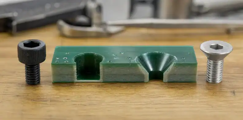
The callout needs pilot diameter, recess diameter, recess depth or included angle, side, quantity, and PTH or NPTH status. Add the drawing revision that governs the feature. If the pilot hole is plated, state which finished diameter controls after plating instead of mixing a mechanical diameter with an unqualified drill size.
For a counterbore, specify the pocket diameter and maximum depth, then state whether the floor may break through a copper-free layer. For a countersink, identify the included angle plus the major diameter or depth that defines the conical boundary. A note such as ‘recess for screw’ leaves the toolpath, tolerance, and controlling side open to interpretation.
| Situation | Preferred treatment | Drawing fields that matter |
|---|---|---|
| Flat-head screw | Countersink | Pilot, large diameter, cone angle or depth, side |
| Socket-head screw | Counterbore | Pilot, pocket diameter, flat depth, side |
| Plated mounting hole | Either only when explicitly designed | Finished hole, plating status, copper keepout |
| Fixture-only clearance | Often neither | Hole size, datum, mechanical purpose |
Protect copper and the remaining laminate
A recess removes dielectric and can approach inner-layer copper, pad annuli, plane clearances, or an adjacent component land. The stackup and the local copper keepout belong in the CAM review. A board that fits one prototype screw can still fail when production material thickness or the cutter path changes.
Check the local stackup before approving a recess under a dense area. The remaining laminate below a pocket can be much thinner than the nominal finished-board thickness when a copper plane, prepreg flow region, or backdrilled feature is nearby. Add a drawing balloon around the feature and show the closest allowed inner copper. This turns a vague clearance concern into a reviewable geometry question.
Drawing rule: A pocket callout needs a depth or angle that an inspector can measure.
Use datums for holes that locate the product
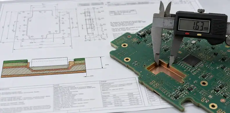
A mounting pattern should be controlled from the same mechanical datum scheme used by the enclosure or fixture. Dimensioning a recess from casual outline edges invites a tolerance stack between routing, drilling, and the mating part. Put critical relationships in the drawing and leave ordinary clearance holes as ordinary features.
A chassis locating pattern needs more than edge dimensions. Use the same reference surfaces that locate the PCB in the housing, then dimension the recess center and pilot hole from that datum scheme. This avoids a fit stack in which routing establishes one origin, drilling uses another, and the enclosure evaluates a third. Ordinary mounting clearance holes can remain less constrained where the screw has genuine freedom.
For the conical alternative, read the existing countersink-hole requirements guidance only for countersink-specific drawing fields; it does not define a flat-bottom pocket.
Separate fabrication feasibility from approval
The fabricator can identify a shallow remaining wall, a cutter reach issue, or a conflict with copper. Engineering decides whether a changed depth, larger board thickness, moved plane, or different fastener remains acceptable. A CAM question should state the measured conflict and the proposed alternative, not silently convert one recess type into the other.
A fabrication response can identify cutter reach, remaining wall thickness, or a recommended recess diameter. It cannot decide that a different screw head is acceptable in the finished product. Record whether engineering accepts the alternative, changes the hardware, or moves the nearby copper. That record matters when a repeat order uses a new board thickness or a revised chassis drawing.
| Recess review point | Evidence | Decision owner |
|---|---|---|
| Selected screw-head geometry | Hardware section and part number | Mechanical design |
| Pocket depth near copper | Stackup section and CAM response | PCB design |
| Pilot-hole finish | Drill callout and plating status | Fabrication engineering |
| First-article seating | Gauge or enclosure fit record | Product quality |
Copper rule: Hold release when the recess encroaches on a defined inner-layer keepout.
Inspect the finished feature in the right order
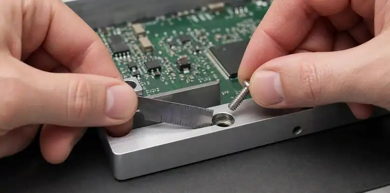
Incoming inspection should first confirm the controlled side and feature count, then compare recess geometry with the drawing and test a representative mating screw or gauge. Photos alone rarely prove depth. For a critical chassis interface, retain the dimensional method and a first-article fit record with the lot documentation.
For critical hardware, inspect the controlled face first because a correct pocket on the opposite side can still pass a simple depth measurement. A depth gauge or optical section can establish the recess geometry; the released screw and enclosure prove seating. Capture both results on the first article when the head is flush with a gasket, shield, or heat-spreader surface.
The recess center also has to respect PCB outline tolerance requirements when the mounting pattern is controlled from the board profile.
Send a quote package that closes ambiguity
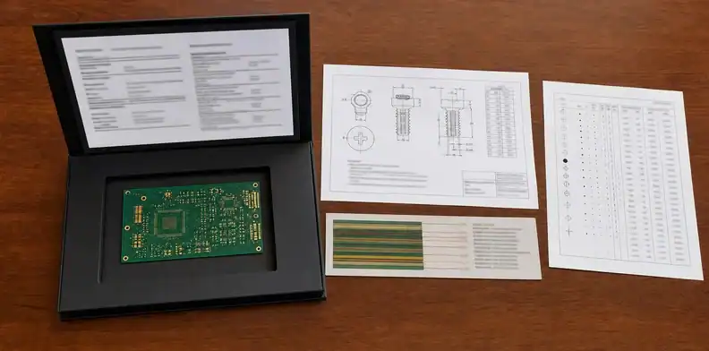
Include Gerber or ODB++, the fabrication drawing, drill table, stackup, local cross-section when the recess is near inner copper, and the fastener or enclosure drawing. QueenEMS can review whether the recess is quoteable and return CAM questions before the mechanical feature becomes an assembly surprise.
The RFQ should include the mechanical fastener drawing, not merely a photograph of the assembled product. Pair it with Gerber or ODB++, drill data, the fabrication drawing, and a stackup view at the recess. This gives CAM enough information to quote a real machining route and lets purchasing compare an exception against a named mechanical interface rather than a generic special hole.
Acceptance rule: Use a real screw or defined gauge for a fit-critical recess.
Resolve a counterbore change without losing the design intent
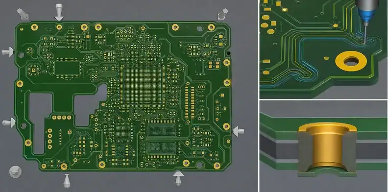
Consider a controller PCB mounted beneath a die-cast cover. The industrial designer wants flat-head screws so the exterior remains flush, while the service team later selects socket-head screws to make field removal easier. The original PCB note says only ‘recessed M3 mounting hole.’ CAM cannot know which outcome governs. The correct review begins with a section through the cover, screw, washer if any, PCB, and the nearest copper layer. If the socket-head option is chosen, the counterbore diameter and depth must leave a floor that supports the head without reducing the board below the allowed local thickness. If the flat-head option remains, the conical angle and major diameter must match the actual screw standard. The engineering record should state who owns the hardware choice, rather than allowing a fabricator to select a recess based on the first sample screw supplied with an RFQ.
A second common case is a plated mounting hole that also carries chassis continuity. The pilot may have a finished diameter and annular-ring requirement, while a shallow counterbore is intended only to clear a screw shoulder. The recess operation can remove outer copper and alter the geometry around the plated barrel, so it needs a local copper map and an explicit controlled side. A useful drawing note identifies the plated pilot, the mechanical recess, the nearest permitted copper, and the inspection method. It does not claim that one generic drill tolerance covers all four. When the supplier proposes a larger cutter or a smaller remaining wall, the response should name the affected hole reference and show the resulting section. That gives engineering enough information to decide whether the grounding interface, fastener torque, and board reliability are still acceptable.
For ongoing production, freeze the successful result in the fabrication package rather than relying on a first-article photograph. Include the fastener part number, the approved recess dimensions, the board face that mates to the chassis, and the revision of the enclosure drawing. A later thickness change, component move, or stackup change can otherwise turn a routine mechanical feature into an inner-layer clearance problem. This is especially important where the recess sits under a shield can, heat spreader, or sealing gasket, because a tiny change in screw seating can create a larger system-level fit issue.
Before release, walk the documentation from the fastener outward. Start with the hardware drawing and record the head shape, bearing surface, head height or angle, and any washer or shoulder. Next, show the controlled PCB face and the pilot-hole condition: plated or non-plated, finished diameter, and relationship to nearby copper. Then add the recess geometry in a form the shop can measure: cylindrical pocket diameter plus depth for a counterbore, or major diameter plus included angle or depth for a countersink. Finally, examine a stackup section at the mounting location and mark the closest inner copper that may not be approached. This sequence catches the failure modes that short notes hide. It also makes quotation more useful, because a fabricator can return a precise question such as insufficient remaining dielectric below MH3 rather than a broad statement that recessed holes need review. For a qualified build, attach the approved screw or a dimensional equivalent to the first-article plan and state whether the result is a fit confirmation, a depth measurement, or both. The released output should let a new buyer, CAM engineer, and receiving inspector reach the same conclusion without reconstructing the mechanical intent from email history.
One final checkpoint is the relationship between the recess and the electrical design. A mounting feature may be close to a ground ring, shield connection, high-voltage clearance, or high-current copper area for good product reasons. Removing material there can change not only mechanical strength but the clearance path and the available land around a plated barrel. Ask the layout owner to review the actual recess envelope on the released layer set, including internal planes. Ask the mechanical owner to confirm torque, seating, and access with the chosen screw. Ask the fabricator to confirm the operation can be performed from the designated side with the requested residual thickness. These three answers should live under one drawing revision. When any answer changes, the job should return to the same cross-functional review rather than treating the new recess depth as a minor manufacturing adjustment.
Set a tolerance boundary for the recess operation
A recess does not need every dimension controlled to the same degree. The pilot-hole axis may be governed by the mounting datum, while pocket depth is limited by remaining laminate and the major diameter is limited by the fastener head. State the dimensions that protect those functions and leave noncritical cutter marks or cosmetic transitions to the fabricator’s normal process. This approach gives CAM a clear boundary for a proposed change: a larger cutter or altered depth can be evaluated against the actual seating and copper-clearance requirement instead of being judged against an overconstrained generic note.
Tolerance rule: Control the recess dimensions that protect hardware seating and construction clearance, not every visible machining detail.
FAQ
Can a plated hole have a counterbore?
Yes, but the drawing must distinguish the finished plated pilot diameter from the mechanically removed recess and show the copper clearance around it.
Is a recess diameter enough?
No. CAM also needs the recess type, depth or included angle, controlled side, and the pilot-hole requirement.
Should a countersink be in Gerber only?
No. Put the governing callout in the fabrication drawing or intelligent manufacturing data and make the design file agree with it.
What should a prototype prove?
A prototype should prove the fastener seats, the board clears the enclosure, and the remaining construction is acceptable before a production drawing is frozen.
Ask for a recess review before the RFQ
Submit the screw drawing, recessed-hole section, pilot-hole data, nearby-layer clearance view, and current fabrication files to QueenEMS. The response can identify the machining constraint and the precise mechanical choice that needs approval.
Sources
Written by the QueenEMS Engineering Team
Upload your files today · Free DFM check before production · Ship worldwide
Get your PCB prototypes in as fast as 24 hours. We handle FR4, Rogers, and hybrid boards up to 40 layers in volume production, with advanced builds subject to engineering review — free prototypes for 2–4 layer FR-4 boards, no minimum order.
Just upload your Gerber + BOM — we source every part, assemble, and inspect (AOI + X‑Ray) so you don't have to chase suppliers. Boards ship in as fast as 24 hours.