
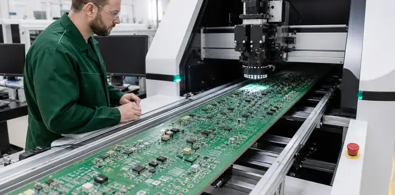
Quick Answer: Large PCB AOI inspection is feasible only when the assembled board, carrier, component height and transport orientation fit the machine and every required feature remains visible and in focus. Approve a coverage matrix before production: AOI for accessible workmanship, AXI or X-ray for concealed joints, and electrical or functional test for behavior that an image cannot prove.
A quoted maximum board length is only the entrance condition. A long assembly may fit inside an AOI platform yet sag outside the usable focus range, collide with conveyor hardware, require two programs, or present hidden joints that no optical camera can see. Buyers should therefore ask for the complete inspection route, not a promise that the board “can run AOI.”
For each defect risk, identify an inspection machine, program and result that can show whether the joint or feature is acceptable. The large PCB inspection plan also addresses dimensions, electrical tests and reporting. Check the assembly equipment limits when the inspection route depends on how the board passes through the rest of the line.
Table of Contents
- Decide whether the whole assembly can enter the inspection route
- Freeze inspection data, fiducials and defect criteria
- Control warpage, focus and field stitching
- Allocate large PCB AOI inspection across AOI, AXI and test
- Qualify the program before trusting pass or fail
- Handle both sides and every board segment
- Release an inspection evidence package
- Quote the complete inspection route
Decide whether the whole assembly can enter the inspection route
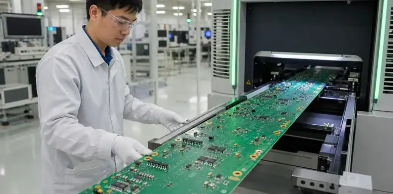
Do not compare the finished PCB outline with one catalog number. Record length, width, thickness, mass, maximum component height on both sides, edge clearance, carrier dimensions and the direction in which the assembly enters. A system may accept a long dimension only in one conveyor orientation; rotating the board can change fiducial visibility, bottom-side clearance and upstream handling.
Equipment limits depend on the model and configuration. Yamaha lists its YSi-V single-lane inspection system for boards up to L610 x W560 mm, with an optional configuration for L750 mm boards. These published dimensions illustrate a specific machine capability; they do not establish a QueenEMS capacity limit or confirm that a populated board and its tooling fit the proposed inspection route.
Separate physical fit from inspectable coverage
Physical fit asks whether the board can load, clamp, travel and unload without collision. Inspectable coverage asks whether cameras can reach the programmed area at the required resolution while the local surface remains inside the allowed height and focus range. A carrier lip, tall connector, overhanging heat sink or cable can pass the transport check and still block evidence.
The same distinction applies to AXI. ViTrox’s published V810i S2 specification lists a 457 × 610 mm maximum panel size but a 434 × 610 mm maximum inspectable area for that model, with top-side clearance dependent on resolution. These figures describe a specific system, not a general AXI limit or a QueenEMS capability. Overlay the required joints and component heights on the quoted configuration; a feature outside its usable inspection region needs another documented method.
Include the loading frame and any mid-span supports in the model. If the board is manually transferred between two inspection positions, define how datum identity and result stitching are preserved. “Two scans” is not yet a route; the overlap, coordinate transformation and uninspected seam require approval.
Record the governing orientation
Mark the leading edge, conveyor width and component-side direction on the assembly drawing. Use the same orientation in the AOI program, work instruction, images and report. If the board must be rotated for a second side or second segment, record a controlled step so serial identity and defect coordinates cannot be swapped.
Freeze inspection data, fiducials and defect criteria
AOI programming begins with controlled design and process data, not with a finished board arriving at the machine. Supply the released Gerber or ODB++, BOM/AVL, centroid, polarity/orientation notes, assembly drawing, approved substitutions and expected solder-joint geometry. Identify unpopulated options and customer-approved deviations so the program does not classify intentional variants as defects.
| Input | Why a large board needs it | Stop condition |
|---|---|---|
| Board outline and conveyor direction | Defines load, clamp and scan coordinates | Machine orientation is ambiguous |
| Global and local fiducials | Controls scale, rotation and local correction | Marks are hidden, damaged or omitted |
| BOM, centroid and polarity | Builds component and orientation library | Uncontrolled substitute or coordinate set |
| Assembly drawing and keepouts | Exposes tall parts, shields and manual areas | Optical access is not defined |
| Defect/acceptance list | Separates process alarms from product disposition | Limits exist only in operator memory |
| Serial or lot method | Links images and calls to a physical unit | Results cannot be reconciled to product |
Long boards magnify small coordinate errors. Use global fiducials to establish the board coordinate system and local fiducials where a dense or mechanically critical region needs tighter correction. Confirm that solder mask, copper balance, panel separation and board support do not distort the fiducial image. A fiducial hidden by a carrier or placed outside the camera path provides no control.
Define defects before setting thresholds: missing/wrong component, polarity, offset, lifted lead, insufficient or excess solder, bridge, tombstone, damaged marking and application-specific connector conditions. The acceptance source and review owner should accompany each class. Otherwise tuning tends to optimize a dashboard score instead of product risk.
Control warpage, focus and field stitching
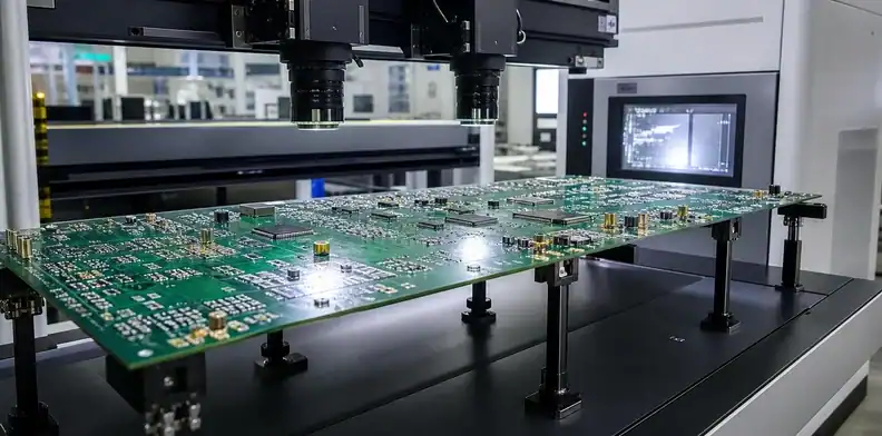
An AOI camera evaluates a local three-dimensional scene. A board that bows several millimeters over a long span can move different regions through the focus and lighting window even though the ends remain clamped. Large components add occlusion and create abrupt height transitions. The inspection fixture must therefore control repeatable shape without hiding pads, side fillets or board identifiers.
Support the board without hiding evidence
Use support locations derived from the assembled mass and board stiffness. Avoid pressing directly beneath fragile bottom components, test points or the joints that must be inspected. Record support height and position as tooling data; an operator adding an improvised post changes board shape, lighting and coordinate registration.
Inspect the free-state and supported board as different conditions. If the assembly only becomes flat when forced into the AOI fixture, determine whether the downstream enclosure uses the same restraint and whether the applied load is acceptable. Passing images cannot justify damaging mechanical preload.
Challenge the worst local height
The first program trial should include the highest component, the deepest shadow, the largest unsupported span and the seam between scan fields. Review focus confidence and repeatability at those points over several load cycles. A single clean image from the center is weak evidence for a one-meter assembly.
Field stitching deserves its own check when the system combines multiple views. Use recognizable features on both sides of each boundary and confirm that a defect near the seam is neither omitted nor counted twice. If the machine handles the board in segments, the coverage report should expose each segment and overlap rather than presenting one unexplained pass icon.
Allocate large PCB AOI inspection across AOI, AXI and test
No inspection technology proves every requirement. Build a coverage matrix that starts with the defect or characteristic, then assigns a primary method and any complementary check. The AOI, X-ray and ICT comparison provides technology background; the large-board decision is whether the required feature lies inside the selected equipment and handling window.
Use AOI for visible evidence
AOI is well suited to programmed inspection of accessible component presence, identity, orientation, placement and visible solder features. It also creates location-specific images that support process tuning. Coverage depends on line of sight, resolution, lighting, library quality and acceptance thresholds. A shield can, tall connector or neighboring component may block a joint that is theoretically on the camera side.
Do not label a component “AOI covered” as one binary field. Separate the attributes: identity may be visible while a bottom-terminated solder joint is not. Record exceptions for manual insertion, post-AOI operations and components added after the programmed route.
Escalate concealed joints deliberately
GÖPEL’s inspection overview distinguishes optical access from X-ray access to concealed joints. BGA, LGA, QFN thermal pads, press-fit barrels and joints beneath shielding may require AXI/X-ray, electrical test, process evidence or a combination.
Electrical test shows behavior or connectivity but may not identify every marginal solder shape. X-ray exposes density differences but does not automatically prove mechanical strength or full functional performance. State the question each method answers and preserve exclusions. This prevents “100% inspected” language from masking a real coverage gap.
Qualify the program before trusting pass or fail
AOI output is a classification decision, not an independent truth source. A new large-board program needs known-good examples, seeded or naturally occurring defect examples where practical, and engineering review of borderline calls. Tune the library and thresholds against product acceptance, then lock the approved program revision.
Start with the first article at normal support and orientation. Review every region that has height, shadow, reflective finish, repeated connectors or field-stitch boundaries. Confirm that polarity and marking libraries match actual approved components, including substitutes. A supplier should not suppress a recurring alarm until the physical joint and acceptance source have been checked.
Track false calls separately from confirmed defects and escapes. High false-call volume increases operator fatigue and can hide real problems; overly permissive thresholds reduce nuisance alarms while increasing escape risk. Siemens’ AOI false-call material is useful background for program improvement, but the project should set its own review and release criteria.
Re-run a small, controlled set after any change to camera recipe, lighting, component library, board support, fiducial strategy or assembly revision. Compare results from repeated loading so the team sees whether a call is process variation or inspection instability. Save representative pass, fail and borderline images with the program revision.
The first-article hold should name who may accept a call and what happens to the remaining quantity. Operator disposition, quality approval and engineering deviation are different authorities. Keep them visible in the traveler.
Handle both sides and every board segment
A double-sided large assembly creates more than a second program. Bottom components may reduce conveyor clearance, prevent flat support or become load points during flipping. Define a fixture and handling method that protects parts and maintains coordinate identity. Link top and bottom results to the same serial number.
Protect transport and board identity
Use edge-clear zones or an approved carrier where the conveyor requires them. If a clamp covers inspection features, establish a controlled second position and report the combined result. Operators should not grab populated spans or rest the assembly on bottom-side components while rotating it.
Apply a durable board/lot identifier before the route stage that generates records. The identifier must survive cleaning and handling and remain visible to the scanner or operator. If the product uses removable travelers, define a reconciliation check before shipment.
Close partial-scan gaps
When the machine scans two halves, list the coordinate range of each program and the verified overlap. When two different machines are used, record program names, calibration state and ownership of the final combined disposition. A pass from machine A cannot silently cover the area assigned to machine B.
Post-AOI operations also create gaps. Hand-soldered connectors, installed shields, reworked components and hardware added after imaging need a downstream check. Mark these process steps in the inspection matrix and prevent final release until their evidence is attached.
For a complex first run, pair the matrix with the staged controls in the large PCB first-article checklist. That keeps program qualification, handling trials and product disposition inside one release sequence rather than separate email chains.
Release an inspection evidence package
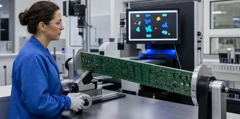
The useful deliverable is not a screenshot of a green dashboard. Request the product part/revision, serial or lot, inspection date, machine and program revision, board orientation, support/carrier revision, result summary, defect list, dispositions and retained images. Include AXI/X-ray or test records referenced by the coverage matrix.
Results should expose scope. Report how many boards and features were inspected, which areas were excluded, which components were manually reviewed and which post-AOI operations occurred. A zero-defect summary without a coverage denominator is difficult to audit and nearly impossible to compare across lots.
For confirmed defects, preserve coordinate, reference designator, defect class, image and disposition. For recurring false calls, preserve the reason and approved program change. For accepted deviations, name the authorizing document and affected quantity. Reworked units should receive the defined post-repair inspection rather than inheriting the original pass.
Review trends at product-relevant levels: defect class, reference designator, scan segment, board position and lot. A concentration near one support post or field seam may indicate inspection setup rather than assembly variation. Conversely, repeating solder findings across the same connector can reveal a manufacturing process issue.
Archive enough raw and summary data to compare repeat orders. If a machine or program changes, the baseline helps determine whether changed calls reflect better detection, different thresholds or real production drift. State retention and customer-delivery expectations before quotation.
| Release record | Question it must answer | Review owner |
|---|---|---|
| Coverage matrix | Which method owns each critical feature? | Product and quality engineering |
| Program/result package | Which revision inspected which serial or lot? | Inspection process owner |
| Exception log | Which gaps, false calls or rework remain? | Authorized disposition owner |
Quote the complete inspection route
Send finished assembly dimensions, thickness, mass, component-height maps for both sides, edge-clearance drawing, Gerber/ODB++, BOM/AVL, centroid, assembly drawing, fiducial details, required standards, critical features and expected lot size. Identify hidden-joint packages, manual operations and the inspection evidence required with shipment.
Ask the supplier to return a station-by-station route:
- machine model/configuration and verified assembly-plus-tooling envelope;
- conveyor orientation, carrier and support arrangement;
- top, bottom and segmented program boundaries;
- AOI feature coverage and declared exclusions;
- AXI/X-ray, electrical and functional supplements;
- first-article program-qualification and approval method;
- per-board/lot traceability, report content and retention;
- response to defects, false calls, rework and process changes.
Do not ask only “Do you have AOI?” A useful response identifies where the complete board travels, how its shape is controlled and which evidence closes each risk. If the route requires manual transfer or two programs, price the handling, programming and review work explicitly.
Use the large PCB RFQ file checklist to package controlled data before supplier review. The quotation should distinguish one-time program/tooling work, first-article evidence and repeat-lot inspection so later commercial comparisons remain meaningful.
Upload the assembly drawing, finished size, component-height map, fiducials, BOM/centroid and inspection matrix through the QueenEMS Large Format PCB page. Ask for a written AOI/AXI route with machine-specific fit, coverage exclusions and shipment evidence before production release.

FAQ
What board size can large-board AOI inspect?
There is no universal size. Published platforms range widely, and usable capacity also depends on conveyor direction, carrier, thickness, mass, component height and support. Confirm the exact factory machine and configuration.
Can AOI inspect BGA solder joints?
AOI can inspect visible package placement and accessible features, but it cannot directly see concealed BGA joints. Assign the hidden-joint question to AXI/X-ray, process evidence and appropriate electrical or functional test.
Does a two-pass AOI scan reduce inspection quality?
Not necessarily, if both coordinate ranges, overlap, fiducials, program revisions and combined disposition are validated. An undocumented seam or manual reposition creates a coverage risk.
Why does warpage affect AOI results?
Warpage moves local features through the camera’s focus and lighting geometry and changes coordinates relative to the programmed plane. Repeatable support and worst-location trials are therefore part of program qualification.
Which AOI records should accompany a large PCB lot?
Request scope and program revision, serial/lot linkage, result summary, confirmed defect/disposition list, critical images, declared exclusions and references to AXI or test evidence.
Sources
Written by the QueenEMS Engineering Team
Upload your files today · Free DFM check before production · Ship worldwide
Get your PCB prototypes in as fast as 24 hours. We handle FR4, Rogers, and hybrid boards up to 40 layers in volume production, with advanced builds subject to engineering review — free prototypes for 2–4 layer FR-4 boards, no minimum order.
Just upload your Gerber + BOM — we source every part, assemble, and inspect (AOI + X‑Ray) so you don't have to chase suppliers. Boards ship in as fast as 24 hours.