
Quick Answer: When comparing selective soldering vs wave soldering, the right choice comes down to your board layout and production volume. Wave soldering processes entire boards in 5 to 10 seconds, making it the cheapest option for high-volume runs (5,000+ units) of purely through-hole components, but it requires $300–$800 custom masking fixtures. Selective soldering is toolless and targets individual pins, making it perfect for complex, double-sided mixed-technology boards while cutting defect rates from a typical 3.2% down to 0.4%.
Key takeaways:
- Wave soldering requires custom masking pallets ($300–$800) that add 1–2 weeks to lead times.
- Selective soldering reduces flux consumption by up to 60% by only spraying targeted areas.
- Hand soldering beats both machine methods on cost if your board has fewer than 5 through-hole pins.
- Hybrid assembly lines run large connectors through the wave first, then selectively solder delicate pins to maximize speed.
Table of Contents
- What Is Wave Soldering and How Does the Process Work?
- What Is Selective Soldering and How Is It Different from Wave Soldering?
- When Should You Choose Selective Soldering Over Wave Soldering?
- When Is Wave Soldering Still the Better Choice?
- How Do Selective and Wave Soldering Compare on Cost, Speed, and Quality?
- What Design Rules Should You Follow for Each Soldering Method?
- Can You Use Both Methods on the Same Board?
- How to Specify Through-Hole Soldering Requirements in Your PCB Assembly Order?
- FAQ
You are reviewing quotes for a new batch of circuit boards, and the assembly pricing seems all over the place. One factory wants to charge you a $500 tooling fee for a “wave pallet,” while another quote skips the tooling fee but charges double for the per-board assembly labor. Sound familiar? After processing 2,400+ assembly orders last year, we see hardware teams constantly overpaying because they choose the wrong through-hole manufacturing process for their specific layout. Here is exactly how to evaluate your mixed assembly design and pick the method that keeps your costs down and your defect rates near zero.
What Is Wave Soldering and How Does the Process Work?
Wave soldering is a high-speed mass production technique where a printed circuit board passes over a cascading pan of molten metal at 245–265°C, soldering hundreds of through-hole pins simultaneously in under 10 seconds. This method washes the entire bottom side of the board in liquid solder, relying on the physical dynamics of a laminar and turbulent wave to push metal up into the plated through-holes.
The process flow follows a strict sequence. First, the machine applies flux across the entire bottom surface using a foam or spray system. Next, the board enters a preheat zone (90–130°C) to activate the flux and prevent thermal shock. Finally, a conveyor drags the board directly over the crest of the molten solder wave.
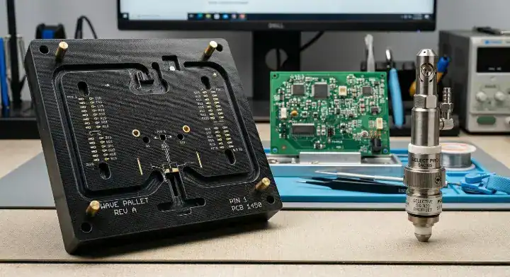
Now, here’s the part that surprises most customers… If you have any Surface Mount Technology (SMT) components already placed on the bottom of that board, the liquid wave will instantly melt them off or short them out. To prevent this, the factory must manufacture a custom-machined fiberglass pallet. This fixture physically covers and masks your sensitive SMT parts, exposing only the through-hole pins to the wave.
The Need for Custom Fixtures (Pallets)
Pallets are not free. Every unique board design requires its own dedicated pallet, which adds upfront NRE (Non-Recurring Engineering) costs and extends your initial lead time by several days while the factory mills the fixture.
| Wave Soldering Characteristic | Typical Specification | Impact on Production |
|---|---|---|
| Board Processing Time | 5 – 10 seconds | Extremely high throughput for mass production |
| Pre-heat Temperature | 90°C – 130°C | Requires gradual ramping to prevent board warping |
| Solder Pot Temperature | 245°C – 265°C | Can damage heat-sensitive plastic connectors |
| Custom Fixture Requirement | Yes (if bottom SMT exists) | Adds $300-$800 to initial setup costs |
The speed of the wave is unmatched, but that speed comes with a heavy reliance on physical masking tools for anything other than a bare bottom layer.
Bottom line: Only select wave soldering if you plan to build thousands of identical boards, as the massive volume offsets the upfront cost of the custom masking pallets.
What Is Selective Soldering and How Is It Different from Wave Soldering?
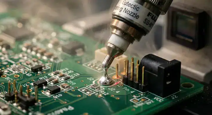
A selective soldering PCB assembly process targets individual through-hole joints using a miniature solder fountain, acting like a programmable robotic arm that completely ignores the rest of the board. Instead of washing the entire bottom layer in liquid metal, a tiny drop-jet nozzle applies flux only to specific pins, and a localized mini-wave performs the soldering joint by joint.
This targeted approach eliminates the need for expensive masking pallets entirely. The machine simply navigates around your bottom-side SMT components.
Here’s where it gets real… Because the nozzle moves independently, engineers can program distinct parameters for every single joint on the board. A massive ground pin connected to a heavy copper plane gets a 3-second dwell time to absorb heat, while a delicate sensor pin right next to it gets a 1-second touch to prevent burning. Wave soldering forces you to compromise with a single temperature for the whole board; selective soldering gives you absolute control.
Factory Veteran View: The Problem: We regularly saw clients experiencing 4% defect rates on high-density boards because the “shadowing effect” in the wave machine prevented solder from reaching pins tucked behind tall capacitors. Our Action: We moved these dense designs to our 5-axis selective soldering line, programming the nozzle to approach the hidden pins from a custom 15-degree angle. The Result: We completely eliminated the shadowing defects, achieving a 99.8% first-pass yield without requiring the client to redesign their layout.
The Role of the Nitrogen Atmosphere
Selective soldering machines operate inside a sealed nitrogen atmosphere. Pumping nitrogen over the mini-wave pushes oxygen out, which stops the solder from oxidizing (creating dross). This creates incredibly shiny, clean joints and significantly reduces the amount of flux in soldering you need to apply, cutting down on post-assembly cleaning requirements.
| Feature | Wave Soldering | Selective Soldering |
|---|---|---|
| Flux Application | Entire board surface | Pinpoint drop-jet targeting |
| Solder Contact | Full board sweep | Individual joint processing |
| Tooling Required | Custom masking pallets | Toolless (Software programming) |
| Joint-Specific Control | Impossible | Fully programmable (Dwell, Temp, Height) |
| Defect Rate | Industry average 2-5% | Typically under 1% |
Switching from a physical fixture to a software-driven path makes selective soldering inherently more flexible for modern hardware designs.
Bottom line: If your board has dense clusters of through-hole pins surrounded by sensitive surface-mount components, selective soldering is the only safe way to process it without risking severe collateral damage.
When Should You Choose Selective Soldering Over Wave Soldering?
You should choose selective soldering over wave soldering whenever you have a double-sided board with SMT components placed on the bottom side, as this prevents you from needing expensive thermal masking glue or custom shielding pallets. Double-sided boards represent the absolute strongest use case for the selective approach in modern manufacturing.
Years ago, engineers placed all surface-mount parts on the top of the board and all through-hole pins on the bottom. Today, miniaturization forces designers to pack SMT components on both sides. If you run a board with bottom-side SMT through a traditional wave, the molten metal will literally wash your tiny 0402 resistors right off the copper pads.
But here’s what most guides won’t tell you… Heat-sensitive components are the second major trigger. Some plastic connector housings, specialized sensors, and relays will melt or warp if exposed to the ambient heat radiating from a massive 260°C wave solder pot. Selective soldering protects these parts by keeping the intense heat strictly confined to a 4mm radius around the metal pin.
Managing Dense Mixed-Technology Layouts
When evaluating SMT vs SMD vs THT technologies, the proximity of the parts dictates the process. If a through-hole pin sits just 2mm away from a dense BGA, the factory cannot physically machine a wave pallet wall thin enough to separate them. The selective nozzle, however, easily glides between tight spaces without touching the BGA.
| Design Factor | Condition Triggering Selective Soldering | Condition Triggering Wave Soldering |
|---|---|---|
| Board Sidedness | Double-sided with bottom SMT | Single-sided or top-SMT only |
| THT to SMT Proximity | Under 3mm clearance | Over 50 mil clearance available |
| Heat Sensitivity | Plastic housings / delicate sensors present | Standard rugged components |
| Flux Residue Tolerance | Very low (Requires minimal flux application) | High (Board will undergo full wash) |
| Production Volume | Low-to-Medium (100 – 5,000 units) | High (10,000+ units) |
The decision heavily favors selective methods as board real estate becomes tighter and component mixes grow more complex.
Bottom line: Audit your bottom layer; if you see surface-mount components sitting within 3mm of your through-hole pins, you must request selective soldering on your RFQ to prevent bridging and thermal damage.
When Is Wave Soldering Still the Better Choice?
Wave soldering through hole components remains the dominant, most cost-effective choice when your board consists of 80% or more THT parts, has a clean bottom layer, and your production volume exceeds 5,000 units annually. For legacy power supplies, industrial controllers, and heavy backplanes, the raw speed of the wave cannot be beaten.
While selective soldering gets all the attention for being high-tech, it is inherently a serial process. The machine solders one pin at a time. If your board has 400 through-hole pins, a selective machine might take 3 to 4 minutes to finish one board. A wave soldering machine will solder all 400 pins simultaneously in roughly 7 seconds.
Want the honest answer? If your layout allows it, the wave is a money-printing machine for high-volume runs.
Factory Veteran View: The Problem: A client requested selective soldering for a massive server power board with 600 heavy-gauge connector pins, complaining about previous wave soldering defect rates. Our Action: We analyzed the layout, realized the bottom side was clean, and moved the job back to the wave line using a custom-engineered titanium pallet to control board warp. The Result: We cut the per-panel assembly time by 45 minutes compared to the selective machine, saving the client $12,000 on their 10k unit production run with zero cold joints.
High-Volume Production Sweet Spots
Large connectors with repetitive pin counts—like PCIe slots, massive terminal blocks, or multi-row headers—are perfect candidates for the wave. The liquid metal naturally flows up the barrels of these massive connectors via capillary action, creating strong, reliable mechanical bonds that handle heavy plugging and unplugging.
| Board Characteristic | Why Wave Soldering Excels Here |
|---|---|
| Single-Sided THT Only | Zero masking required; fastest possible throughput |
| 5,000+ Unit Volumes | Setup costs amortize quickly; per-board labor drops to pennies |
| Massive Pin Counts (300+) | Simultaneous soldering beats serial point-to-point speed |
| Heavy Copper Planes | Massive solder pot provides instant thermal transfer to heavy ground planes |
For simple boards moving at massive scale, the traditional wave remains the absolute king of the factory floor.
Bottom line: If you are designing a pure power supply or a simple interface board meant for 10,000-unit runs, explicitly keep all SMT components on the top layer so you can exploit the cheap, lightning-fast speed of wave soldering.
How Do Selective and Wave Soldering Compare on Cost, Speed, and Quality?
While a selective vs wave soldering cost analysis shows that selective machine hourly rates are roughly three times more expensive, selective soldering often yields a significantly lower Total Cost of Ownership (TCO) by dropping defect rates from a typical 3.2% down to 0.4%. You have to factor in the hidden labor costs of manual rework to get an accurate picture.
Engineers routinely underestimate the financial impact of post-wave manual touch-ups. If a wave machine leaves solder bridges on 3% of your boards, a technician must sit at a bench with a soldering iron, physically wick away the excess solder, and re-test the board. That manual labor costs you $45 to $75 an hour.
The real question is: Where is the breakeven point? Sierra Assembly tracked a real-world case study for an industrial motor control unit. When they switched from a masked wave process to selective soldering, the initial first-pass yield jumped from 89% to 99.2%. The reduction in scrap boards and rework hours completely erased the fact that the selective machine took 2 minutes longer per board to run.
Calculating the True Cost Structure
Selective soldering requires zero tooling. If you use the wave on a mixed board, you pay $500 for a pallet. If your volume is only 500 boards, that pallet adds $1.00 of hidden cost to every single board before the machine even turns on.
| Cost / Performance Metric | Wave Soldering | Selective Soldering | Hand Soldering |
|---|---|---|---|
| NRE / Fixture Setup Cost | $300 – $800 (Pallet required) | $0 (Software programming only) | $0 |
| Processing Speed | 5 – 10 seconds (Entire board) | 1 – 3 minutes (Point-by-point) | 5 – 10 minutes |
| Typical Defect Rate | 2% – 5% (Requires rework) | < 1% (Highly repeatable) | 10% – 15% (Human error) |
| Flux / Solder Consumption | Very High (Washes whole board) | Very Low (Micro-drops only) | Minimal |
| Best Volume Sweet Spot | 5,000+ units | 100 – 5,000 units | 1 – 50 units (Prototypes) |
Relying on hand soldering as a third option only makes financial sense if your board has fewer than 5 through-hole pins; anything more, and machine consistency wins.
Bottom line: Base your decision on Total Cost of Ownership; pay the higher per-board selective soldering fee for runs under 5,000 units to completely eliminate the tooling fees and manual rework costs associated with the wave.
What Design Rules Should You Follow for Each Soldering Method?
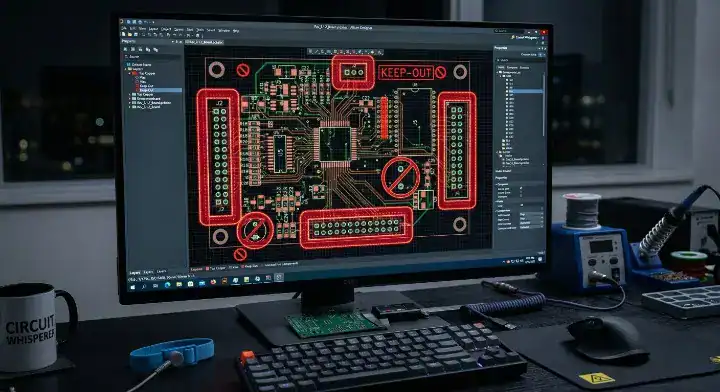
Wave soldering requires strict component orientation parallel to the wave direction and massive 50-to-100 mil keep-out zones, whereas selective soldering allows for much tighter 3mm clearances around target pins. Following the correct Design for Manufacturing (DFM) rules prevents your factory from kicking your design back for layout modifications.
When you route a board destined for the wave, the physical direction the board travels on the conveyor matters. If you place a long, rectangular dual-in-line package (DIP) perpendicular to the wave, the solder will crash into the side of the plastic body, leaving the trailing pins starved of solder. This causes the dreaded “shadowing effect,” leading directly to cold solder joints that fail in the field.
So what does this actually mean for your layout? For wave soldering, you must align all polarized components and multi-pin connectors parallel to the flow. You must also add “thieving pads” (dummy copper pads) at the trailing edge of fine-pitch components to drag excess solder away and prevent bridging. Selective soldering completely ignores orientation rules because the nozzle moves in 360 degrees.
Factory Veteran View: The Problem: A client submitted a dense layout for wave soldering, but the fine-pitch connector at the trailing edge kept developing massive solder bridges across the last three pins. Our Action: We stepped in during the DFM phase and added 50-mil thieving pads to the trailing edge of the connector footprint in their CAD files. The Result: The dummy pads pulled the excess liquid solder away from the active pins exactly as designed, resulting in zero bridging defects across the 2,000-unit run.
Clearance and Keep-Out Zones
For wave soldering with a pallet, you need space for the fiberglass wall. You must leave at least 50 mils (1.27mm) of bare FR4 between your through-hole pad and the nearest SMT component. If you plan to use selective soldering, the keep-out zone shrinks, but you still need about 3mm of clearance for the 6mm drop-jet nozzle to safely maneuver without bumping a capacitor.
| DFM Rule Category | Wave Soldering Requirement | Selective Soldering Requirement |
|---|---|---|
| Component Orientation | Must be parallel to wave flow | Any orientation acceptable |
| Keep-Out Zones (Clearance) | 50 – 100 mils (For pallet walls) | ~3mm (For nozzle clearance) |
| Thieving Pads | Mandatory on trailing edges | Not required |
| Tall Component Spacing | Beware of trailing shadow zones | Nozzle navigates around tall parts |
Designing specifically for the machine you plan to use drops your manufacturing lead time by days.
Bottom line: If your board real estate is extremely tight and you cannot afford 100-mil keep-out zones for pallet walls, you must design your layout assuming selective soldering will be used.
Can You Use Both Methods on the Same Board?
Yes, many advanced contract manufacturers utilize a hybrid approach on complex THT PCB assembly runs, sending massive power connectors through the fast wave soldering machine first, then routing the board to the selective soldering line for delicate, fine-pitch through-hole components. This hybrid process maximizes throughput while protecting sensitive components.
Not every factory has the capability or the engineering team to pull this off. It requires precise process planning. If you have a telecom board featuring three massive 200-pin backplane connectors alongside a cluster of heat-sensitive optical sensors, neither process alone works perfectly.
Here’s where it gets real… The production line flow looks like this: First, the board goes through the SMT reflow oven. Second, the factory applies a simple, cheap masking tape to the delicate optical sensor holes and runs the massive connectors through the wave. Finally, they peel the tape and run the board through the selective machine, precisely soldering the delicate optical sensors in a nitrogen atmosphere.
When Hybrid Manufacturing Makes Sense
This approach requires the factory to own both types of expensive machinery, which is why many low-tier suppliers will push you toward 100% hand soldering for the remaining parts instead. Hand soldering works fine for one or two odd components, but if you have a dense cluster of delicate pins, the hybrid machine approach guarantees repeatability.
| Assembly Approach | Production Line Sequence | Best Used For |
|---|---|---|
| Standard Wave | SMT Reflow -> Wave Solder | Simple boards, 80%+ THT components |
| Standard Selective | SMT Reflow -> Selective Solder | Double-sided boards, high density |
| Hybrid Approach | Reflow -> Wave (Large parts) -> Selective (Delicate parts) | Complex industrial/telecom boards |
| Manual Fallback | Reflow -> Wave -> Hand Solder | Boards with fewer than 5 remaining delicate pins |
Only partner with an EMS provider that actively maintains both wave and selective lines under one roof to keep this hybrid option open.
Bottom line: Ask your contract manufacturer if they support hybrid process planning; using the wave for the bulk work and the selective nozzle for precision finishing cuts both your cycle time and your defect rate simultaneously.
How to Specify Through-Hole Soldering Requirements in Your PCB Assembly Order?

To specify your requirements clearly, state exactly which process you need in your assembly drawing notes by writing “Selective soldering required for U4 and J2 to prevent thermal damage,” rather than leaving the process choice up to the factory floor operator. Vague instructions force the factory to guess, usually leading them to pick whichever machine is currently sitting idle.
Purchasing managers frequently send over a Bill of Materials (BOM) and Gerbers and simply ask for “assembly.” This is a mistake. The choice between wave and selective soldering drastically alters your final invoice due to tooling costs.
Want the honest answer? If you are unsure which method is better, ask the factory to make a recommendation based on a formal DFM review. Do not just accept a quote that includes a $600 tooling fee without asking the account manager, “Could we run this toolless on your selective line instead?”
Writing Clear Assembly Notes
Place your processing requirements directly on your fab drawing layer or in a prominent ReadMe file. If your board requires selective soldering because of heat-sensitive components, list those specific reference designators.
| Specification Method | What to Write in the RFQ or Drawing | Resulting Action from the CM |
|---|---|---|
| Process Mandate | “Must use Selective Soldering. No wave pallets allowed.” | CM quotes machine time, zero tooling fees. |
| Component Protection | “Selective solder J1-J4. Heat sensitive housing.” | CM routes specific pins to the targeted nozzle. |
| DFM Request | “Please review for Wave vs Selective viability.” | CM engineers evaluate clearance and suggest cheapest route. |
| Wash Requirements | “No-clean flux required for selective pass.” | CM adjusts chemical process to prevent residue. |
Being explicit in your documentation prevents expensive rework disputes after the boards are delivered.
Bottom line: Never submit an RFQ for a mixed-technology board without explicitly requesting a DFM review to compare the tooling costs of wave soldering against the programming costs of selective soldering for your specific layout.
Choosing between selective and wave soldering shouldn’t feel like a gamble—now you have the decision framework and design rules to pick the exact process that minimizes your setup fees and eliminates post-assembly rework. At QueenEMS, we offer full turnkey services with completely transparent pricing, maintaining both advanced wave and 5-axis selective soldering lines in-house. We provide a free DFM/DFA engineering review on every single order, actively advising you on which process yields the lowest Total Cost of Ownership for your specific board density. We believe every hardware team deserves a manufacturing partner who explains their processes, not hides them. Contact us today to get a side-by-side quote for both options.
Written by the QueenEMS Engineering Team
FAQ
1.Can selective soldering handle thick backplane boards with heavy copper planes? Yes, it can. While wave soldering provides excellent bulk heat transfer, modern selective machines use programmable pre-heaters and extended nozzle dwell times to safely punch heat through thick 3oz copper planes. This allows for deep barrel fill on heavy backplanes without thermally shocking the surrounding components. Upload your BOM for a free DFM check and we will verify your thermal relief requirements.
2.Does wave soldering always require cleaning the board afterward? It depends on the flux chemistry used. If the factory uses a water-soluble flux in the wave machine, a thorough wash cycle is mandatory to prevent long-term corrosion. If they use a no-clean flux, washing is technically optional, though many high-reliability clients still request it. Because selective soldering applies 60% less flux, it is much easier to leave unwashed. Get a transparent quote within 24 hours to review our no-clean process options.
3.Is hand soldering cheaper than setting up a selective soldering machine? Yes, but only for extreme low-volume prototypes or boards that have fewer than 5 through-hole pins. Programming a selective machine takes an engineer 30 to 60 minutes. If you only need 10 boards built with two through-hole resistors each, paying a technician to hand-solder them for 15 minutes is far more economical. Request a free first-article inspection on your first order to see our manual soldering quality firsthand.
Upload your files today · Free DFM check before production · Ship worldwide
Get your PCB prototypes in as fast as 24 hours. We handle FR4, Rogers, and Flex up to 60 layers — free prototypes for 2–4 layer boards, no minimum order.
Just upload your Gerber + BOM — we source every part, assemble, and inspect (AOI + X‑Ray) so you don't have to chase suppliers. Boards ship in as fast as 24 hours.