
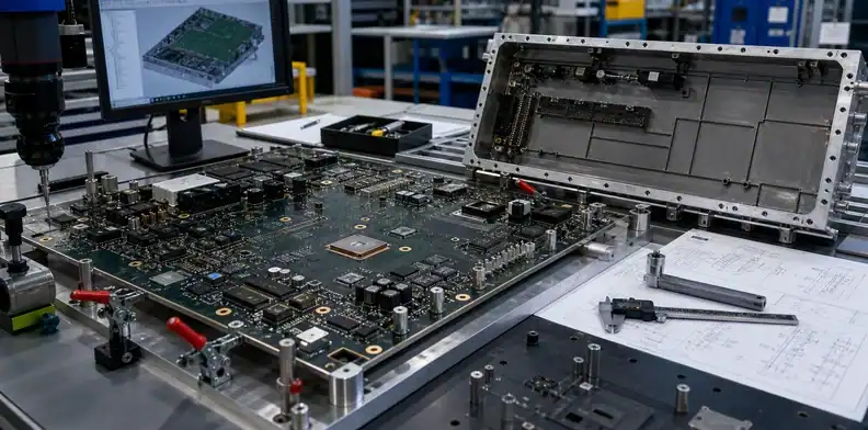
Quick Answer: A large PCB first article should prove the released files, materials, tooling, assembly process, mechanical fit and test method before the rest of the lot proceeds. Put hold points before irreversible or expensive operations. Release only the quantity and characteristics supported by measurements, inspection records and approved deviations.
Large boards can concentrate cost and schedule risk when the outline leaves unused panel area, requires dedicated tooling or complicates handling. A late mechanical mismatch can affect an entire enclosure or rack. Waiting until the full batch reaches final test can turn one open assumption into many expensive units.
A staged first-article review lets the team resolve setup and interface problems before committing the rest of an oversized lot. Use the large PCB inspection plan for flatness, datums, electrical tests and reporting. Keep the distinction between first article inspection and AOI clear: an optical inspection result alone does not replace product validation or the agreed first-article evidence.
Table of Contents
- Define what the first article must prove
- Freeze the configuration before material release
- Place hold points along the expensive route
- Inspect the bare large PCB
- Validate assembly setup and thermal behavior
- Prove mechanical fit and functional test
- Close deviations and create the baseline
- Quote an executable first-article plan
Define what the first article must prove
The plan should connect each critical requirement to a method, result and release owner. It is not a ceremonial inspection of whichever unit finishes first.
Separate product conformance from process readiness
Product conformance asks whether the article matches drawing, BOM, workmanship, electrical and functional requirements. Process readiness asks whether the intended materials, programs, tooling, equipment and controls produced that result repeatably enough to continue the authorized lot.
A passing dimension does not approve a wrong laminate, substitute component or unrecorded manual route. Likewise, correct product data does not approve an unvalidated carrier or test fixture. Put both questions in the plan and assign evidence to each.
Define the release boundary
State what may continue after every approval. Bare-board approval may release routing of the remaining panel, shipment to assembly or only selected measurements. SMT setup approval may release a small pilot rather than the full quantity. Final article approval may authorize the balance only after open defects and deviations are closed.
The release boundary prevents “first article” from becoming a vague green light. Purchasing records the quantity at risk; engineering owns design and interface intent; manufacturing owns process setup; quality confirms evidence and disposition.
Freeze the configuration before material release
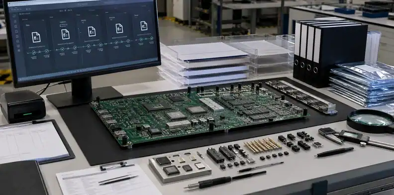
Every measured result must trace to one controlled configuration. Freeze Gerber or ODB++, drill data, stack-up, drawing, BOM/AVL, centroid, assembly instructions, firmware, test procedure, mechanical model, carrier and fixture revisions before the first article begins.
| Configuration item | First-article check | Stop condition |
|---|---|---|
| PCB data and drawing | Matching part/revision and checksum | Mixed or superseded files |
| Stack-up and materials | Approved construction and substitutions | Unapproved material/build |
| BOM/AVL and centroid | Correct MPN, polarity, quantity and coordinates | Ambiguous or unavailable part |
| Tooling/programs | Named stencil, placement, oven, AOI and test revisions | Uncontrolled setup |
| Mechanical interface | Current enclosure, connector and support model | Mating definition incomplete |
| Acceptance sources | Agreed standards, limits and customer notes | Method or limit missing |
Record approved temporary conditions separately. A prototype part, hand-solder operation or surrogate load may support design learning but cannot silently become the production baseline.
Configuration rule: Stop when the article cannot be tied to one released data, material, program and tooling set.
Place hold points along the expensive route
Large-board risk is reduced by stopping before value is added to a wrong configuration. Choose hold points where a failure can still be corrected without scrapping the whole lot.
Review processed data before irreversible work
CAM questions should close outline, datum, hole, stack-up, copper, impedance and panel/tooling assumptions before imaging or lamination. Approve supplier-processed data where the project requires it. For unusual size, verify production-panel orientation and coupon/tooling placement rather than reviewing only the finished outline.
An early laminate or drill setup coupon may be useful when critical holes, registration or special materials drive risk. The first-article plan should say what is checked and whether the balance may proceed.
Release assembly in controlled increments
Do not automatically populate every expensive bare board after one fabrication pass. Use an agreed first-article or pilot quantity that supports printing, placement, reflow, inspection, mechanical fit and test. Quantity follows risk, destructive checks, fixture development and variation—not a universal number.
Place holds after paste/SPI setup, first placement verification, reflow profile confirmation and first completed PCBA as appropriate. The traveler must show who releases the next quantity and how rejected material is identified.
Set the quantity-at-risk explicitly at each hold. Some operations can proceed on panels that do not depend on the open characteristic; others should remain stopped because later separation, finish or assembly would destroy the opportunity to correct the issue. The plan should state that boundary before the line is waiting, not during a production-pressure phone call.
Schedule also affects the hold design. Customer witness, external laboratory work or enclosure availability can create long waits. Protect material during the pause with defined storage, moisture, ESD and support conditions, and record exposure time where components or finishes require it. A conforming first article can be damaged while awaiting approval if the queue condition is uncontrolled.
Inspect the bare large PCB
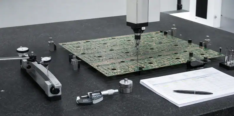
Bare-board evidence should focus on features that become hard to measure or impossible to correct after assembly. Size and shape must be measured in the support condition defined by the product drawing.
Verify outline, datums, holes and flatness
Measure overall dimensions, critical connector/mounting relationships, finished holes and slots, thickness, bow/twist and any application-specific positional characteristics. Tie results to the board/panel, measurement equipment and drawing revision.
Do not press a board flat unless the approved method requires that condition. Report free-state and fixture-supported results separately when both matter. A board can pass a general flatness limit yet fail a connector alignment or chassis-fit requirement.
Confirm electrical and structural evidence
Review electrical-test coverage and result, impedance coupon data where required, microsection or plating evidence selected by the plan, surface finish, solder mask and edge quality. Destructive evidence comes from qualified coupons or designated samples; the plan must account for quantity consumed.
Link findings to the large PCB RFQ file package so repeat orders preserve the same drawing notes and records instead of rebuilding acceptance from email history.
Decision point: Every hold approval must name the exact quantity and downstream operations it releases.
Validate assembly setup and thermal behavior
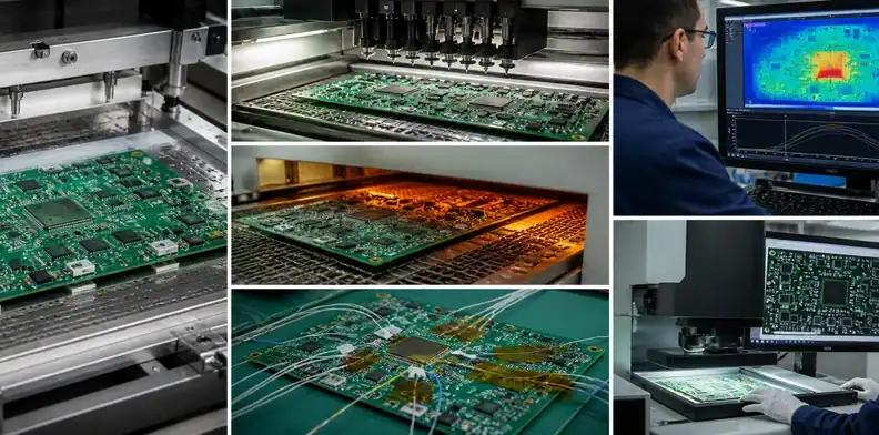
The first PCBA should prove that printer support, stencil, placement coordinates, fiducials, reflow profile, carrier and inspection programs fit the actual oversized board.
Review paste deposition in difficult or split-print regions, component identity/orientation, connector position, support contact and any manual placement. Record program revisions and exceptions. A green machine status is not enough when portions of the board were outside normal automation.
Use a populated thermal-profile vehicle and the intended carrier. The existing reflow profile optimization background explains the general thermal process; for this first article, the approved paste/component limits and supplier profile record remain controlling.
After reflow, inspect visible joints, targeted hidden joints, board shape, displaced components and tooling/contact marks. Any rework on the first article must be recorded, because an extensively reworked sample cannot prove that the initial process was ready for the remaining lot.
Separate correction of setup from correction of design. A wrong polarity in the placement program may be fixed without changing the product definition; insufficient land pattern, inaccessible test point or incompatible connector position returns to engineering. The deviation log should name which domain owns the cause so the response is not reduced to cosmetic rework.
Retain solder-paste inspection, AOI and X-ray images that represent both conforming and rejected conditions. Those records help approve program thresholds and provide a comparison if the remaining lot begins to drift. Store them with the program revision rather than as anonymous screenshots.
| Assembly hold | Evidence reviewed | Authorized next step |
|---|---|---|
| Paste setup | Stencil, support and SPI result | First placement only |
| Placement check | Identity, orientation and coordinates | Reflow of pilot units |
| Thermal release | Profile and carrier revision | Controlled reflow route |
| Completed PCBA | Inspection, shape and rework record | Fit and functional test |
Prove mechanical fit and functional test
Large boards often fail at the system boundary rather than at bare-board continuity. Install the article with production-representative hardware, connectors, rails, stiffeners, heat sinks and cable loads.
Measure mating and installed shape
Verify connector alignment, enclosure cutouts, standoff contact, screw seating, insertion force and accessible service clearances. Measure board shape before and after fastening when restraint matters. Do not use excessive screw torque or connector force to hide misalignment.
Record hardware revision, torque where controlled, support sequence and actual results. A temporary 3D-printed enclosure may support design learning but should be identified if it does not represent production tolerances or material behavior.
Challenge the test method
Electrical continuity, in-circuit test, boundary scan, programming, functional test and system test answer different questions. Define coverage, fixtures, software/firmware revision, expected values and failure response. A large fixture also needs support that prevents probe force from bending the PCB and creating false failures.
Use known-good and known-failure conditions where practical to show that the fixture and software detect what they claim. Record exclusions; “functional test passed” should never imply 100% coverage of untested interfaces.
For a contextual first-article review, pair the critical-characteristic list, hold points and evidence matrix with this PCB DFM review guide. The resulting supplier plan should be executable and should clearly identify validation that remains under customer ownership.
Process rule: A reworked first article cannot by itself approve an uncorrected initial process.
Close deviations and create the baseline
Release requires disposition of every nonconformance and open assumption. Classify each item as corrected, use-as-is with authorization, rework with verification, scrap or deferred under a controlled temporary action.
A deviation record should name the affected serial/lot, requirement, actual result, technical assessment, authorization, expiration or affected quantity and whether drawings/programs must change. Verbal acceptance is not a repeat-order baseline.
At minimum, the closure record must expose:
- the affected serial number, lot and characteristic;
- the requirement and measured result;
- the correction, rework or use-as-is decision;
- the named engineering or quality approver;
- the revised drawing, program, fixture or instruction when applicable;
- the quantity and expiry of any temporary containment.
Close measurement anomalies as carefully as product defects. A result near a limit may reflect fixture repeatability, probe loading or datum setup rather than the PCB. Repeat measurement with a defined method, confirm gauge suitability and document the disposition. Silently selecting the most favorable reading breaks traceability.
The release meeting should review open items by consequence: product safety/function, manufacturability, inspection coverage, delivery and repeat-order control. A conditional release needs an owner, expiry and containment for the exact remaining quantity. It is not permission to carry the same exception indefinitely.
The final package contains the approved product revisions, materials, route, tooling/program versions, raw and summary inspection results, profile report, fit/test evidence, photos, deviations and signatures. Define delta-FAI triggers for design, material, source, site, program, tooling, process or fixture changes. Routine production still needs process control; the first article does not replace lot inspection.
A connector change may leave the outline unchanged while invalidating part of the assembly first article. In this illustrative review, retain unaffected dimensional results only after checking their configuration traceability, and repeat the affected part-identity, placement, thermal-exposure, mating-fit and electrical checks. Record which earlier results remain valid and why. L3Harris-BCS supplier guidance similarly requires renewed FAI when changes invalidate original results. Its contractual forms and approval rules apply to its purchasing requirements, not automatically to every PCB order.
Receiving should know which records travel with the shipment and which remain available on request. Tie certificate, inspection report, packaging label and board serial or lot identity together. If the receiving team cannot reconcile delivered units with the approved baseline, quarantine the shipment until traceability is restored rather than recreating acceptance from screenshots and email.
A common failure is to close the visible defect but leave the released program or drawing unchanged. The first repaired unit may pass, yet the next lot repeats the original condition. Close the loop by linking every corrective action to the revised file, program, fixture or work instruction and by naming the revision that repeat production must use.
Quote an executable first-article plan
The supplier cannot price “FAI required” accurately without knowing the characteristics, methods, documents and approval path. Send the controlled product package plus a characteristic matrix that names the source requirement, method, sample quantity, report format and approver.
Specify destructive checks, customer witness points, fixture ownership, profile deliverables, mechanical-fit hardware, firmware/test responsibilities, retained samples and release timing. Ask the supplier to identify which operations stop and which can continue at risk.
Request a report index before the PO so both teams agree on deliverable names and formats. Dimensional results should reference characteristic IDs; images should identify serial and location; electrical and functional logs should preserve limits as well as results. This avoids receiving a stack of files that cannot be reconciled with the drawing.
Commercial terms should identify who pays for repeat setup or renewed first-article work when the customer changes data, the supplier proposes a process change or the original article fails. Keeping those cases visible prevents technical approval from being delayed by an undefined charge after material is already committed.
Quotation request: Provide the released fabrication and assembly data, critical-characteristic matrix, mating-hardware definition, test procedure and planned quantity using the QueenEMS oversized PCB enquiry. The commercial response should separate first-article engineering, tooling, destructive evidence and production quantity, with a named release point for each stage.
Release rule: Close or formally contain every deviation before copying the baseline to repeat production.

FAQ
How many large PCB first articles should I order?
Choose enough units for required destructive evidence, profile instrumentation, fixture development, assembly-fit checks and expected variation. There is no universal count; document what each unit is intended to prove.
Is a first article the same as a prototype?
No. A prototype may use temporary materials or processes for design learning. A first article should represent the intended production configuration and route unless deviations are explicitly identified.
Can AOI approval release the lot?
No by itself. AOI covers visible programmed features; it does not prove material, hidden joints, dimensions, electrical behavior, firmware, mechanical fit or the complete production setup.
Should the remaining lot wait for system fit?
Yes when system fit is a critical requirement and later correction would create unacceptable risk. The approved plan may allow limited parallel work only with a recorded quantity-at-risk decision.
What changes trigger a new first-article review?
Review design revision, material/source, manufacturing site, critical equipment/program, tooling, fixture, process and acceptance-method changes. The impact assessment decides whether full or partial revalidation is required.
Sources
- NASA GSFC-STD-8001: Printed Circuit Board Quality Requirements
- Caltech/LIGO: Printed Circuit Board Checklist Prior to Manufacture
Written by the QueenEMS Engineering Team
Upload your files today · Free DFM check before production · Ship worldwide
Get your PCB prototypes in as fast as 24 hours. We handle FR4, Rogers, and hybrid boards up to 40 layers in volume production, with advanced builds subject to engineering review — free prototypes for 2–4 layer FR-4 boards, no minimum order.
Just upload your Gerber + BOM — we source every part, assemble, and inspect (AOI + X‑Ray) so you don't have to chase suppliers. Boards ship in as fast as 24 hours.