
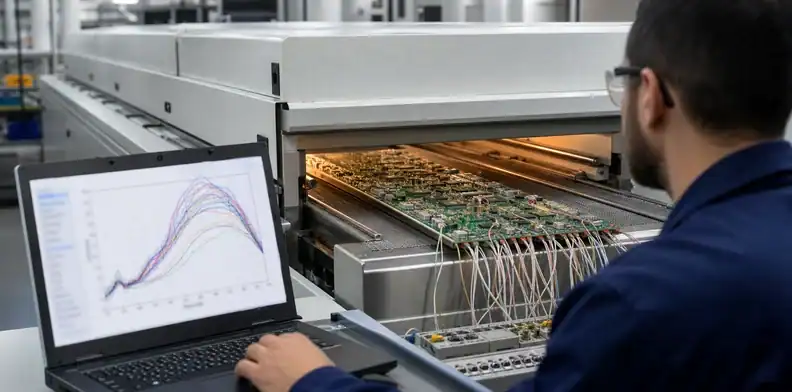
Quick Answer: A large PCB thermal profile needs thermocouples on representative cold, hot and temperature-sensitive locations of a populated assembly. Run the intended carrier, orientation and loading pattern. Approve the oven recipe only when every valid channel meets the applicable paste and component limits and solder inspection also passes.
A wide temperature spread can hide behind one apparently good trace. The thermocouple near a light board edge may show acceptable peak temperature while a copper-rich connector field remains below the required reflow condition. Raising the oven to fix the cold joint can then overheat a small device or connector housing elsewhere.
Large PCB thermal profiling is therefore a measurement-planning problem before it becomes an oven-setting problem. This article focuses on profile vehicle, thermocouple location, attachment, channel interpretation and release records. Carrier construction belongs to the large PCB reflow carrier decision, while broader line feasibility belongs to large-format PCB assembly qualification.
Table of Contents
- Build a representative profile vehicle
- Map thermal mass before placing sensors
- Attach thermocouples to the measured joint
- Profile the loaded route and orientation
- Read hot, cold and sensitive channels together
- Respond to an excessive temperature spread
- Release a reproducible profile baseline
- Control changes and reprofile triggers
- Prepare a profile-ready RFQ
Build a representative profile vehicle
The profile vehicle must match the intended assembly closely enough to reproduce its heat absorption, airflow exposure and support condition. A bare PCB is not an adequate substitute for a populated product when large copper areas, connectors, shields or power components dominate the response.
Match the production configuration
Use the released board revision, stack-up, copper construction, solder paste, component population, carrier and fixtures planned for production. Include thermal interface hardware or shields that are present during reflow. Record controlled omissions when an expensive component is replaced by a thermally representative surrogate; engineering must approve the substitution.
Indium Corporation notes that bare and populated boards can differ materially during profiling and recommends using a populated assembly. The practical consequence is clear: do not approve a recipe from a convenient scrap laminate that lacks the product’s thermal mass.
Preserve traceability after instrumenting the board
Give the profile vehicle an ID and link it to PCB revision, BOM revision, paste lot/type, carrier revision, oven line and thermocouple map. Photograph attachment points before the run and record damaged pads, drilled access holes or removed parts. An instrumented board is evidence only when reviewers can reconstruct what it represented.
Keep the thermocouple channel name consistent across the location photograph, profiler software, exported raw file and approval report. If a sensor is replaced, record the new attachment and channel mapping instead of overwriting the failed run. This chain prevents a valid curve from being attributed to the wrong joint or assembly revision during later review.
Map thermal mass before placing sensors
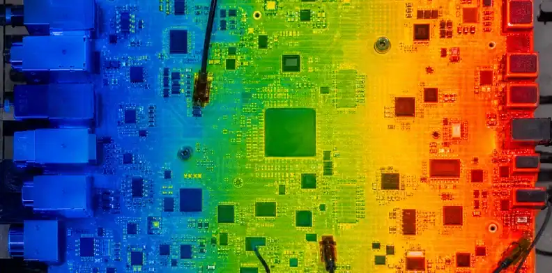
Thermocouple locations should be selected from a thermal-risk map, not spaced evenly for visual symmetry. Identify regions likely to heat slowly, heat quickly or approach a component’s process limit.
| Risk region | Typical cause | Sensor target | Question answered |
|---|---|---|---|
| Cold high-mass zone | Ground planes, large connector, shield or heat sink | Representative solder joint in that region | Did the slowest joint complete the required profile? |
| Hot low-mass zone | Sparse copper, small component, exposed edge | Small solder joint or sensitive package area | Did the fastest region exceed its limit? |
| Center span | Distance from edges and altered airflow | Central joint near representative population | Is the middle lagging the perimeter? |
| Carrier/contact zone | Support shadow or added mass | Joint near support boundary | Is tooling changing local heating? |
| Sensitive device | Connector housing, LED, relay or special package | Manufacturer-defined body/joint point | Does the component remain inside its rating? |
Use schematic power function, copper artwork, component mass and carrier contact to build the map. The number of channels follows the number of distinct risks; a long board does not earn fewer sensors because the profiler has limited inputs. If necessary, run controlled repeat profiles with overlapping reference channels.
Sensor rule: Every thermocouple must answer a named hot, cold, center, tooling or component-limit question.
Attach thermocouples to the measured joint
A thermal trace is credible only when the junction measures the intended location and remains attached through the run. Loose wire, insulation between the tip and joint, or a junction formed away from the tip can produce a smooth but false curve.
Put the junction where the decision is made
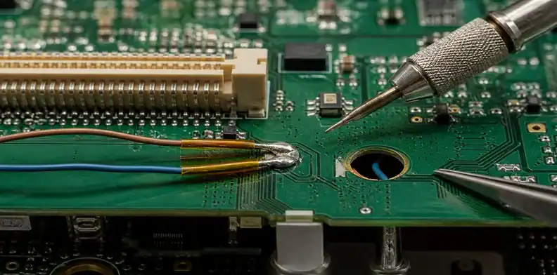
For solder-process validation, place the welded tip in contact with the target solder joint rather than on a nearby board surface. Bottom-terminated components may require a small access hole so the sensor reaches the joint under the package. Component-body limits may require a separate sensor at the housing location defined by the manufacturer.
Avoid choosing only easily accessible joints. A convenient perimeter pad cannot represent an inner BGA ball, a large ground termination or a connector core. The attachment plan should explain why each location is thermally meaningful.
Use an attachment method that survives reflow
High-temperature solder attachment is commonly preferred for joint measurement when compatible with the run. Thermally conductive epoxy or correctly applied aluminum tape can be alternatives. Indium’s application note warns that insulating tape can distort the reading and that twisted thermocouple wires may create an unintended measurement junction.
Route the wires so they do not lift the tip, shadow airflow, interfere with the carrier or pull the board. Keep the profiler far enough behind the assembly that its mass does not change the board’s thermal environment. Perform a continuity and room-temperature plausibility check before entering the oven.
| Attachment fault | Likely trace symptom | Required action |
|---|---|---|
| Junction lifts from the joint | Abrupt or air-like response | Reattach and repeat the run |
| Wire junction forms before the tip | Wrong physical location measured | Replace the thermocouple |
| Insulating tape covers the target | Delayed, damped response | Use a qualified attachment method |
| Lead pulls on the junction | Intermittent steps | Reroute and secure the wire |
Profile the loaded route and orientation
Run the exact conveyor orientation, rail setting, center support, carrier and board spacing intended for production. Thermal behavior can change when the long axis rotates, when a carrier is added or when adjacent assemblies alter airflow.
Include the carrier as part of the process
A carrier can add heat capacity and create local shielding. Profile the production carrier revision, including retainers and supports. Do not copy a no-carrier recipe to a carried board or assume a carrier redesign is thermally neutral.
Measure the loaded envelope separately from temperature. Confirm that thermocouple wires and profiler hardware clear transfers, curtains and unloaders. Mechanical interference can invalidate the run before the data is collected.
Carrier identification should include material, thickness, cutout pattern, support locations and hardware condition. A nominally identical carrier with worn retainers or a different support contact can change both heat flow and board shape. Retain a drawing or controlled photograph with the released profile so production can reproduce the qualified configuration.
Reproduce spacing and conveyor conditions
Board-to-board spacing affects oven loading and recovery. Define whether the qualification uses a single board, a production pitch or a worst-case loading pattern. Record conveyor speed, zone setpoints, fan/convection settings where available and board orientation.
The recipe name should identify product and revision rather than rely on an informal “large board” program. A line change, maintenance event or different oven needs a controlled transfer or fresh verification.
Measurement rule: A smooth curve is not valid evidence until junction location and attachment remain verified.
Read hot, cold and sensitive channels together
Release is based on the intersection of all applicable windows. The cold joint must achieve the solder-paste requirements while the hottest joint and sensitive components remain below their limits.
Review ramp behavior, soak interval when specified, time above liquidus, peak temperature and cooling against the approved paste data and component constraints. Do not publish one universal profile number; alloys, paste formulations, packages and product requirements differ. Attach the current technical data sheet or customer specification to the release record.
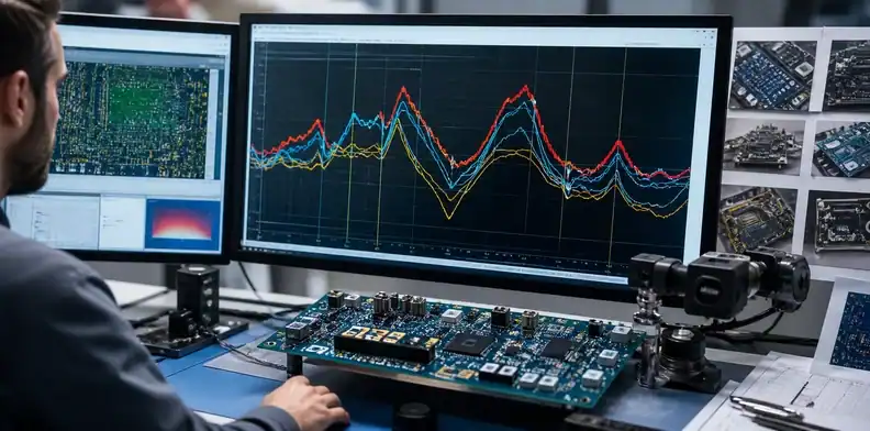
Calculate channel-to-channel spread at relevant moments rather than comparing peaks alone. One region may peak later, making the real conflict visible in time-above-liquidus or soak behavior. Overlay all traces and label each physical location so reviewers can connect the graph to the assembly.
Inspect the raw curve for sensor faults before calculating pass/fail. A sudden step, flat line, implausible oscillation or one channel that tracks oven air rather than the board may indicate a loose junction or damaged wire. KIC’s thermocouple troubleshooting guidance identifies attachment failure as a cause of a channel starting to follow air temperature. Repair the attachment and repeat the profile; do not delete the failed channel to turn the original run into a passing report. Preserve rejected traces and the reason for rejection.
The coldest and hottest channels can change after a layout or BOM revision. A substituted connector, shield, transformer or copper-heavy power section may move the limiting point. Do not retain sensor positions merely because they were used on the previous revision; rebuild the risk map and document why any old location remains representative.
A passing profile does not waive solder-joint inspection, and a visually acceptable joint cannot waive a component temperature limit. Correlate valid traces with SPI where used, post-reflow visual/AOI results, targeted X-ray for hidden joints and any product-specific evidence. When those results conflict, investigate deposition, wetting, materials and support rather than treating a passing curve as a release. Both measurement validity and assembly acceptance must be resolved.
| Channel role | Primary result | Release question |
|---|---|---|
| Cold high-mass joint | Time above liquidus and peak | Did the slowest solder joint reach its approved window? |
| Hot low-mass joint | Ramp, peak and exposure | Did the fastest region remain below its limit? |
| Sensitive component | Body or manufacturer-defined point | Was the component-specific maximum respected? |
| Carrier-affected region | Trace shape versus nearby joint | Did support or shielding create a local exception? |
Respond to an excessive temperature spread
An excessive hot-to-cold difference should trigger a structured process and design review. Raising all zone temperatures is rarely the first safe answer because it can consume the margin of the fastest-heating region.
Adjust the process within component and paste limits
Possible process changes include zone balance, conveyor speed, top/bottom heater relationship, airflow settings, board spacing or orientation. Change one controlled group at a time, rerun the complete sensor set and retain both before-and-after traces.
The acceptable adjustment depends on the oven and product. A recipe that needs an extreme setting or leaves little margin may be unstable across normal equipment variation; manufacturing engineering should decide whether it is suitable for repeat production.
Revisit tooling or product heat distribution
Carrier cutouts and support material can reduce local heat shadow when mechanical stiffness remains adequate. Heavy shields or heat sinks may be installed later when the product allows it. Copper distribution, thermal spokes, component selection or board segmentation are design decisions and require product-engineering approval.
Use the large PCB warpage review when temperature differences and support interact with board shape. The objective is not merely a passing thermal graph but a soldered assembly that remains dimensionally and mechanically acceptable.
A DFM review before production can help identify likely hot and cold locations and thermocouple-access concerns. Include the stack-up, BOM, assembly drawings, solder-paste data, carrier drawing and proposed sensor positions so the review can identify which thermal-profile measurements are needed for the first lot.
Decision point: Adjust the recipe only after all hot, cold and sensitive channels are interpreted together.
Release a reproducible profile baseline
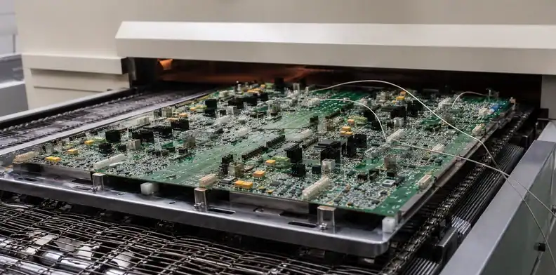
The release package should let another qualified reviewer reproduce the run. Store the profile vehicle ID, thermocouple map and photos, attachment method, oven/line, recipe revision, conveyor direction, carrier revision, loading pattern, raw channel data, calculated results, inspection findings and approvals.
Define ownership for archived raw data as well as the summary PDF. Raw channels allow later reviewers to re-evaluate a defect against the actual time-temperature history, while a screenshot may omit sampling detail or individual traces. Link the production lot to the active recipe and carrier revision so a field or receiving investigation can identify whether the approved profile was in force.
Before release, confirm that the archive contains the profile-vehicle and product revisions, a labeled thermocouple map, attachment photographs, oven identity, loading configuration, raw traces, acceptance calculations, applicable paste/component limits and correlated solder-inspection results. Missing context is a release issue: a curve without a physical channel map cannot prove which joint was measured.
Evidence rule: Do not approve a thermal baseline that cannot be reconstructed from its archived files.
Control changes and reprofile triggers
A released recipe remains valid only while production matches the qualified board, component, paste, carrier and oven conditions. Define reprofile triggers before the first lot so engineering can distinguish routine verification from a process-development restart.
Triggers normally include a PCB stack-up or copper change, a BOM substitution with different thermal mass, paste/alloy change, carrier revision, board orientation change, oven transfer, major equipment maintenance or a solder-defect trend. Not every change requires a complete redevelopment, but each needs a documented impact assessment.
Monitor production with the controls agreed for the line: recipe lock, periodic oven checks, verification interval and reaction plan. A profile report is a baseline, not permanent proof that every later run followed the same thermal process.
For transferred production, compare oven geometry and control capability before copying setpoints. The same displayed zone temperatures and conveyor speed do not guarantee the same board response on another machine. Run the instrumented vehicle, compare channel outcomes and issue a new site/line approval when the transfer changes the qualified condition.
Change rule: Reprofile whenever the production condition no longer represents the approved thermal baseline.
Prepare a profile-ready RFQ
A meaningful quote needs the files that determine profile complexity and validation effort. Send Gerber or ODB++, stack-up, BOM/AVL, centroid, assembly drawings, 3D component heights, paste/alloy requirements, temperature-sensitive component data, carrier concept, expected quantity and inspection/test scope.
State whether the supplier must develop the recipe, provide raw traces, submit a thermocouple map, retain the vehicle or repeat profiling at production transfer. Identify customer-required limits and approval owners. This separates routine setup from special engineering work and makes two quotations comparable.
Also define how many profile runs and sacrificial assemblies the quotation includes. Instrumentation can damage pads or components, and troubleshooting may consume more than one vehicle. Clarify ownership and storage of the instrumented board, replacement components and raw profiler files so a later repeat run does not begin with missing evidence.
Quotation request: Upload the released thermal inputs and proposed production configuration through the Large Format PCB manufacturing page. Ask QueenEMS to return the proposed profile-vehicle plan, thermocouple locations, carrier dependency, validation deliverables and any unresolved component temperature constraints with the assembly quotation.
Release rule: Lock the recipe only when critical channels, carrier condition and correlated solder evidence pass.
FAQ
Can I profile a large PCB without components?
No for final production release. A bare board may support an early experiment, but it does not reproduce the populated assembly’s thermal mass and cannot validate the production recipe.
Where should thermocouples go on a long board?
Place them at representative cold high-mass joints, hot low-mass joints, the center span, carrier-shadow regions and temperature-sensitive components. Every location should answer a named risk question.
Is Kapton tape acceptable for thermocouple attachment?
Not as the default precision method. Insulating tape can change the response or lose contact; use a qualified attachment method that holds the junction at the measured joint.
Does a reflow carrier require a new thermal profile?
Yes when it changes thermal mass, shielding, support or airflow relative to the qualified condition. Treat carrier revision as a profile-impact trigger.
Should every production lot be reprofiled?
Not automatically. Define periodic checks and change triggers from process risk, customer requirements and line controls; reprofile when the approved baseline no longer represents production.
Sources
- Indium Corporation: Attaching Thermocouples to a PCB for Reflow Profiling
- Amphenol Communications Solutions: DFM and SMT Assembly Guideline TB-2305
Written by the QueenEMS Engineering Team
Upload your files today · Free DFM check before production · Ship worldwide
Get your PCB prototypes in as fast as 24 hours. We handle FR4, Rogers, and hybrid boards up to 40 layers in volume production, with advanced builds subject to engineering review — free prototypes for 2–4 layer FR-4 boards, no minimum order.
Just upload your Gerber + BOM — we source every part, assemble, and inspect (AOI + X‑Ray) so you don't have to chase suppliers. Boards ship in as fast as 24 hours.