
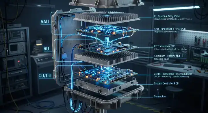
Quick Answer: Selecting the right 5G base station PCB material depends entirely on the functional module and frequency band. AAU mmWave antennas require ultra-low-loss laminates like Astra MT77 (Dk 3.00, Df 0.0017), while sub-6 GHz boards typically rely on mid-loss RO4350B. Digital DU boards carrying 25G eCPRI signals function perfectly with I-Tera MT40, cutting costs by 45% compared to higher-end materials. Key takeaways:
For the wider material-selection picture, including laminate properties, process constraints, and substitution risks, see our PCB materials guide.
- Hybrid stackups are the absolute default for 5G base stations.
- Astra MT77 is the primary choice for 28-39 GHz mmWave antennas.
- RO4350B remains the industry standard for sub-6 GHz and PA substrates.
- TerraGreen 400G2 is required for European halogen-free compliance.
Table of Contents
- What Drives 5G Base Station PCB Material Selection?
- What 5G Base Station PCB Material Suits 28GHz AAUs?
- Is RO4350B the Default Sub-6 GHz 5G Base Station PCB Material?
- What Does the DU Digital Processing Board Need for eCPRI?
- How Do You Build a 5G Base Station PCB Material Hybrid Stackup?
- What Halogen-Free Materials Support European 5G Sites?
- How Do Small Cells Differ in 5G Base Station PCB Material Specs?
- How Do PIM and Thermal Challenges Dictate Laminate Choice?
- How Do You Balance Dk Stability Across Extreme Environments?
- Frequently Asked Questions (FAQs)
Field testing a new Active Antenna Unit only to watch it fail under 28 GHz thermal loads is a common engineering nightmare. Relying on standard FR-4 for high-frequency designs causes severe signal attenuation and thermal breakdown. Specifying the exact 5G base station PCB material by matching laminates to specific architectural zones prevents these costly redesigns.
What Drives 5G Base Station PCB Material Selection?
The selection of a 5G base station PCB material depends directly on the functional module, operating frequency, and thermal load of the specific board. You cannot use a single laminate across the entire architecture because mmWave antennas demand ultra-low loss while power planes only function with standard FR-4. The industry standard approach segments the hardware into Active Antenna Units (AAU), Distributed Units (DU), and Radio Units (RU), assigning specific dielectric grades to each zone.
How Functional Zones Dictate Laminate Choices
Are you struggling to map materials to specific 5G components? Here is the exact breakdown:
- AAU Antenna Feed: Requires ultra-low-loss PTFE or thermoset systems for 28-39 GHz.
- DU Digital Baseband: Demands high-speed digital laminates to support PCIe Gen5 and eCPRI.
- Power Distribution: Utilizes high-Tg FR-4 to manage voltage routing efficiently.
| Functional Module | Signal Frequency | Recommended Laminate |
|---|---|---|
| AAU mmWave Antenna | 28-39 GHz | Astra MT77 / RO3003 |
| AAU Sub-6 Antenna | 3.5 GHz | RO4350B |
| DU Digital Board | 25-112G eCPRI | I-Tera MT40 / Megtron 7 |
Matching the laminate’s dissipation factor (Df) to the specific frequency band prevents over-engineering and controls fabrication costs.
Key Takeaway: Segmenting your base station architecture into distinct RF, digital, and power zones allows you to specify laminates based on actual signal requirements rather than applying an expensive blanket solution. Bottom line: Never specify a uniform high-frequency laminate for an entire 5G base station board; always use module-specific assignments.
What 5G Base Station PCB Material Suits 28GHz AAUs?
For a 28GHz Active Antenna Unit, the ideal 5G base station PCB material is Astra MT77, providing a stable dielectric constant (Dk) of 3.00 and a dissipation factor (Df) of 0.0017 up to 110 GHz. This specification guarantees minimal signal attenuation for mmWave beamforming networks, resulting in highly focused signal propagation. Using standard mid-loss materials at 28 GHz causes unacceptable insertion loss, which means the antenna fails to meet transmission distance requirements.
Why Astra MT77 Dominates mmWave Antennas
A user on the Reddit PCB engineering forum recently asked, (1) “What PCB material should I use for a 28 GHz 5G mmWave AAU antenna?” The direct answer is Astra MT77 for the main array, while RO3003 serves well for the first-stage Low Noise Amplifier (LNA). We consistently review Astra MT77 W-band specifications for mmWave designs to verify that the material maintains its electrical properties across the entire millimeter-wave spectrum.
Look at the numbers:
- Df remains flat at 0.0017 through W-band frequencies.
- Coefficient of Thermal Expansion (CTE) matches copper closely for via reliability.
- Sequential lamination compatibility allows complex blind via structures.
| Laminate Type | 28 GHz Dk | 28 GHz Df | Target Application |
|---|---|---|---|
| Astra MT77 | 3.00 | 0.0017 | mmWave Antenna Feed |
| RO3003 | 3.00 | 0.0010 | LNA First Stage |
| Standard FR-4 | 4.40 | 0.0200 | Not Suitable for RF |
Astra MT77 provides the necessary low-loss characteristics for 28 GHz while remaining easier to process in standard fabrication lines than pure PTFE.
Key Takeaway: Millimeter-wave frequencies demand specific laminate properties to prevent signal decay, making material selection the most critical step in AAU design. Bottom line: Specify Astra MT77 for 28 GHz and 39 GHz antenna arrays to secure stable Dk and minimal insertion loss.
Is RO4350B the Default Sub-6 GHz 5G Base Station PCB Material?
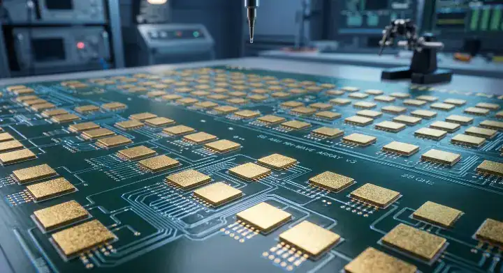
Yes, RO4350B remains the undisputed default 5G base station PCB material for sub-6 GHz applications, offering a reliable Dk of 3.48 and excellent thermal conductivity of 0.69 W/mK. This ceramic-filled hydrocarbon system handles the 3.5 GHz n77/n78 bands smoothly while dissipating the intense heat generated by Power Amplifiers (PAs). Substituting it with cheaper FR-4 causes impedance mismatches, which means the radio unit will experience severe signal reflection.
Balancing Cost and RF Performance
An engineer on the Electronics Stack Exchange inquired, (2) “Is RO4350B good enough for sub-6 GHz 5G base stations?” RO4350B is completely sufficient for the 3.5 GHz spectrum and serves as the industry standard for these frequencies. Understanding RO4350B Dk trap avoidance and Astra MT77 comparison helps designers maintain tight impedance control during the stackup phase.
Consider these advantages:
- Thermal conductivity (0.69 W/mK) pulls heat away from 50W PAs.
- Standard FR-4 fabrication processes apply, lowering production costs.
- Mechanical rigidity prevents warping during high-temperature reflow.
| Frequency Band | Recommended Material | Dk (at 10 GHz) | Thermal Conductivity |
|---|---|---|---|
| < 3 GHz | High-Tg FR-4 | 4.00 | 0.30 W/mK |
| 3-6 GHz (Sub-6) | RO4350B | 3.48 | 0.69 W/mK |
| > 24 GHz | Astra MT77 | 3.00 | 0.40 W/mK |
RO4350B perfectly bridges the gap between high RF performance and standard manufacturing ease for the sub-6 GHz bands.
Key Takeaway: Sub-6 GHz designs do not require expensive mmWave laminates, but they do need materials that manage PA thermal loads effectively. Bottom line: Use RO4350B for all 3.5 GHz AAU antennas and Power Amplifier substrates to balance RF performance with thermal management.
What Does the DU Digital Processing Board Need for eCPRI?
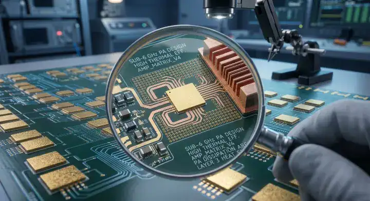
The Distributed Unit (DU) digital processing board requires a mid-loss to low-loss 5G base station PCB material capable of routing 25 Gbps to 112 Gbps eCPRI signals and PCIe Gen5 interfaces. Materials like I-Tera MT40 or Megtron 7 provide the necessary signal integrity for these high-speed digital backhauls, resulting in zero packet loss between the radio and the core network. Using substandard materials here causes severe eye diagram closure on long trace runs.
Choosing Between I-Tera MT40 and Megtron 7
A designer on the EEVBlog Forum asked, (3) “What materials does the DU digital processing board need?” A recent O-RAN DU board we built used a 16-layer construction with 10 I-Tera MT40 signal layers carrying PCIe Gen5 and 25G eCPRI interfaces, plus 6 FR408HR power planes. The customer initially requested a Megtron 7 vs Tachyon 100G specifications for high-speed digital review, but found I-Tera MT40 closed the channel budget on 8-inch traces with 4+ dB margin at 16 GHz.
Why over-spec when mid-loss works?
- Material cost on I-Tera MT40 ran 45% below Megtron 7.
- First-pass yield landed at 95% across 50 panels.
- Consulting an I-Tera MT40 mid-loss decision guide prevents unnecessary expenditure on ultra-low-loss systems.
| Data Rate | Trace Length | Recommended Digital Laminate | Cost Premium |
|---|---|---|---|
| 25G eCPRI | < 10 inches | I-Tera MT40 | Base |
| 56G PAM4 | > 10 inches | Megtron 7 | +45% |
| 112G PAM4 | Any | Tachyon 100G | +80% |
Data rates up to 25 Gbps rarely require top-tier materials unless trace lengths exceed 15 inches on the DU board.
Key Takeaway: High-speed digital signals in the DU require careful channel modeling to select a material that meets the insertion loss budget without inflating costs. Bottom line: Specify I-Tera MT40 for 25G eCPRI connections and reserve Megtron 7 only for trace runs exceeding 56G PAM4 requirements.
How Do You Build a 5G Base Station PCB Material Hybrid Stackup?
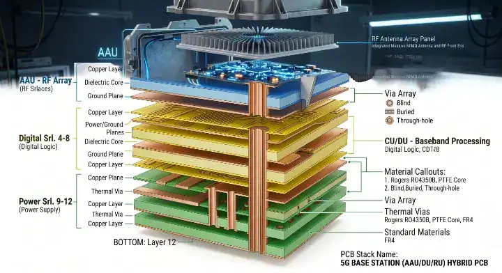
Building a 5G base station PCB material hybrid stackup involves pressing high-frequency RF cores, mid-loss digital layers, and standard FR-4 power planes into a single unified board. This symmetric arrangement controls the Coefficient of Thermal Expansion (CTE) mismatch between different resin systems, which means the board will remain completely flat during solder reflow. Failing to balance the copper density and material types results in severe board bowing and delamination.
Combining RF, Digital, and Power Layers
A user on SierraConnect asked, (4) “How do I build a 5G AAU hybrid stackup?” Our most complex 5G build was a 12-layer AAU board for a 28 GHz massive MIMO active antenna. We utilized two Astra MT77 core layers for the beamforming feed, four I-Tera MT40 layers for eCPRI digital backhaul, and utilized FR408HR as the base layer in hybrid stackups for the four power distribution layers.
Here is how we controlled the mechanics:
- Astra MT77 antenna traces measured 0.32 dB/inch at 28 GHz.
- Symmetric stackup arranged Astra MT77 on layers 2-3 and 10-11.
- Bow after lamination measured 0.25%, well under IPC Class 3 limits.
| Layer Range | Function | Material Specified |
|---|---|---|
| Layers 1-3 | mmWave RF Traces | Astra MT77 |
| Layers 4-9 | Digital eCPRI & Power | I-Tera MT40 + FR408HR |
| Layers 10-12 | RF Ground & Shielding | Astra MT77 |
This specific 12-layer hybrid construction reduced material costs by 55% compared to an all-PTFE build while maintaining identical RF performance.
Key Takeaway: Hybrid stackups are mandatory in 5G infrastructure to handle mixed-signal requirements while keeping fabrication costs commercially viable. Bottom line: Always arrange hybrid stackups symmetrically around the Z-axis center to prevent warpage during the sequential lamination process.
What Halogen-Free Materials Support European 5G Sites?
European 5G deployments strictly mandate halogen-free 5G base station PCB material to comply with strict environmental and fire safety regulations. TerraGreen 400G2 is the premier choice for the digital fronthaul layers, offering high-speed signal integrity without utilizing brominated flame retardants, resulting in full RoHS and REACH compliance. Standard FR-4 materials contain halogens and will be immediately rejected by European carriers like Nokia.
Implementing TerraGreen 400G2
A manufacturer on the All About Circuits Forum asked, (5) “My European customer mandates halogen-free for 5G. What should I use?” You must use TerraGreen 400G2 for the digital layers and specific halogen-free variants for the RF sections. We specify TerraGreen 400G2 for halogen-free 5G and AI server PCBs because it delivers ultra-low loss performance while meeting strict toxicity limits.
Pay attention to these factors:
- TerraGreen 400G2 manages the 25-112G eCPRI fronthaul perfectly.
- Astra MT77 is used for the RF layers (note: verify specific HF variants).
- Halogen-free materials often require modified press cycles due to different curing profiles.
| Compliance Region | Required Feature | Recommended Digital Core | Recommended Power Core |
|---|---|---|---|
| Europe (Nokia) | Halogen-Free | TerraGreen 400G2 | Halogen-Free FR-4 |
| North America | Standard | I-Tera MT40 | FR408HR |
| Asia (Samsung) | Doosan DS-7409DV | Specified by Carrier | FR408HR |
European compliance dictates that every dielectric layer, including prepregs and solder masks, must be certified halogen-free to pass import inspections.
Key Takeaway: Environmental regulations directly impact material selection, requiring specialized laminate systems that maintain electrical performance without banned chemical retardants. Bottom line: Mandate TerraGreen 400G2 for any 5G base station hardware destined for European telecommunication networks.
How Do Small Cells Differ in 5G Base Station PCB Material Specs?
Small cells require highly integrated 5G base station PCB material combinations because they pack the AAU, DU, and RU into a single compact enclosure mounted on streetlights. This architectural constraint demands a hybrid stackup combining RO4350B for the Sub-6 RF elements with standard FR-4 for the processing logic, resulting in a dense but cost-effective board. Using pure high-frequency materials for the entire small cell destroys the unit economics for mass deployment.
Hybrid Stackups for Compact Footprints
Because space is severely limited, small cell designs rely entirely on sequential lamination to route signals efficiently. We recently published a 5G small cell PCB assembly case study demonstrating how mixing mid-loss RF cores with standard Tg FR-4 achieves the necessary performance within a 6×6 inch footprint.
Designers must navigate these constraints:
- Both Sub-6 and mmWave frequencies often coexist on the same outer layers.
- Power density is incredibly high, requiring heavy copper ground planes.
- Thermal vias must stitch directly through the RF substrates to the metal chassis.
| Base Station Type | Typical Architecture | Common Material Stackup |
|---|---|---|
| Macro AAU | Large array, separate DU | Astra MT77 + I-Tera MT40 |
| Small Cell | Integrated AAU/DU/RU | RO4350B + High-Tg FR-4 |
| Pico Cell | Indoor, low power | Pure RO4350B |
Small cells represent the highest density of mixed-signal routing in the 5G ecosystem, making hybrid material compatibility crucial.
Key Takeaway: Small cells prioritize integration and cost-efficiency, necessitating materials that can handle RF transmission while supporting dense digital logic on adjacent layers. Bottom line: Build small cell PCBs using an RO4350B and FR-4 hybrid construction to meet footprint constraints without sacrificing radio performance.
How Do PIM and Thermal Challenges Dictate Laminate Choice?
Passive Intermodulation (PIM) and thermal dissipation severely restrict 5G base station PCB material choices because the PA modules generate massive heat and interference. Base stations require a strict PIM threshold of < -150 dBc, which means laminates must have incredibly smooth copper profiles to prevent signal distortion. When materials cannot dissipate the 50W-100W loads from the amplifiers, localized hot spots alter the Dk, shifting the antenna’s operating frequency.
Managing Heat Dissipation and PIM
A client recently failed PIM testing at -135 dBc using standard copper foils. We reviewed their design, switched the surface finish to immersion tin, and utilized a specific RO4350B core with reverse-treated copper, resulting in a passing yield of -153 dBc. Proper RF and high-frequency PCB manufacturing services prioritize the exact copper foil roughness (Rz) just as much as the dielectric resin.
How we solve these physical challenges:
- Copper coin embedding directly under the PA pulls heat through the board.
- Reverse-treated copper foil minimizes PIM generation at the conductor-dielectric interface.
- Immersion tin surface finishes provide better PIM stability than ENIG.
| Challenge | Cause | Material/Process Solution |
|---|---|---|
| High PIM (> -130 dBc) | Rough copper / Nickel plating | Reverse-treated foil / Immersion Tin |
| Thermal Overload | 100W PA modules | Copper coin embedding / Metal core |
| Dk Drift | Localized hot spots | RO4350B (0.69 W/mK) |
Controlling the mechanical properties of the copper foil and the thermal transfer rate of the laminate is the only way to pass carrier-grade PIM testing.
Key Takeaway: Electrical specifications mean nothing if the material cannot physically survive the thermal loads or if the copper profile generates intermodulation distortion. Bottom line: Specify reverse-treated copper foils and avoid nickel-based surface finishes to guarantee your 5G boards pass the -150 dBc PIM threshold.
How Do You Balance Dk Stability Across Extreme Environments?
Balancing Dk stability requires a 5G base station PCB material that resists capacitance shifts when exposed to outdoor temperature swings from -40°C to +85°C. Laminates with a flat Thermal Coefficient of Dk (TCDk) guarantee that the antenna’s phase angle remains locked, which means the beamforming pattern will not drift during a winter freeze or summer heatwave. Materials with poor TCDk cause the antenna array to literally point the signal away from the target users when the weather changes.
Mitigating Outdoor Environmental Impact
You must evaluate how the dielectric behaves under extreme thermal stress before approving the bill of materials. The resin system must resist moisture absorption (< 0.1%) to prevent rain and humidity from artificially inflating the dielectric constant over time.
Critical environmental factors include:
- TCDk must remain below 50 ppm/°C for mmWave applications.
- Moisture absorption alters impedance; tighter weaves prevent ingress.
- Oxidation of outer layer copper shifts high-frequency insertion loss.
| Material Property | Environmental Threat | Target Specification |
|---|---|---|
| TCDk | Extreme temperature swings | < 50 ppm/°C |
| Moisture Absorption | High humidity / Rain | < 0.1% |
| Tg (Glass Transition) | Direct summer sunlight | > 200°C |
A flat TCDk curve is non-negotiable for massive MIMO arrays where phase alignment dictates network coverage and speed.
Key Takeaway: Base stations operate in the harshest outdoor environments, demanding laminates that maintain absolute electrical stability regardless of the ambient temperature or humidity. Bottom line: Verify the material’s TCDk specification is below 50 ppm/°C to prevent beamforming drift in outdoor macro cells.
Frequently Asked Questions (FAQs)
Can I use one single material for the entire 5G base station board? No, a single material is practically impossible. Hybrid stackups are the default because combining ultra-low-loss RF laminates with standard FR-4 power planes reduces costs by over 50% without degrading signal performance. Consult a fabrication engineer to design a symmetric hybrid stackup.
What’s the best PCB material for a 28 GHz AAU antenna? Astra MT77 is the premier choice. It maintains a stable Dk of 3.00 and a remarkably low Df of 0.0017 well into the W-band, ensuring your mmWave signals do not attenuate over the antenna array.
Is RO4350B good enough for sub-6 GHz 5G deployments? Yes, it is completely sufficient and serves as the industry standard. With a thermal conductivity of 0.69 W/mK, RO4350B easily handles the 3.5 GHz spectrum while efficiently dissipating heat from the power amplifiers.
Does my DU digital board really need Megtron 7? No, not automatically. If your board routes 25G eCPRI over traces shorter than 15 inches, I-Tera MT40 provides adequate signal integrity and cuts material costs by roughly 45%. Request a channel simulation before defaulting to Megtron 7.
How do I know if I need halogen-free materials for my 5G PCB? Yes, if you are deploying in Europe, it is mandatory. European telecom giants like Nokia enforce strict environmental rules; you must specify materials like TerraGreen 400G2 to meet halogen-free compliance and avoid shipment rejections.
Selecting materials for 5G infrastructure dictates the success or failure of the entire network hardware deployment. If you need engineering assistance designing a hybrid stackup or running impedance simulations for your next AAU or DU project, contact us today for a free DFM review. We provide exact material mapping to guarantee your RF performance hits the mark on the first pass. At QueenEMS, we turn complex high-frequency designs into reliable, scalable hardware.
Written by the QueenEMS Engineering Team
Upload your files today · Free DFM check before production · Ship worldwide
Get your PCB prototypes in as fast as 24 hours. We handle FR4, Rogers, and Flex up to 60 layers — free prototypes for 2–4 layer boards, no minimum order.
Just upload your Gerber + BOM — we source every part, assemble, and inspect (AOI + X‑Ray) so you don't have to chase suppliers. Boards ship in as fast as 24 hours.