
I-Tera MT40 is Isola’s mid-loss, FR-4-process-compatible laminate with Dk 3.45 and Df 0.0031 at 10 GHz, positioned as the cost-effective sweet spot for PCIe Gen4/5, DDR5, and 25G-56G Ethernet designs where ultra-low-loss materials like Tachyon 100G are unnecessary.
“Do I really need Tachyon 100G (Df 0.0021), or is I-Tera MT40 (Df 0.0031) good enough?” This is the most common material selection question we receive from hardware engineers. This guide details the exact performance boundaries of I-Tera MT40, the unique Dk tuning of its RF/MW variant, and a clear framework for deciding when to use it and when to upgrade.
Table of Contents
- What Is I-Tera MT40 and Why Is It Isola’s Most Popular High-Speed Material?
- What Electrical and Thermal Properties Define I-Tera MT40?
- Where Does I-Tera MT40 Sit in Isola’s Four-Tier Portfolio?
- What Makes the RF/MW Variant with 4 Dk Options Unique?
- When Is I-Tera MT40 Enough, and When Must You Upgrade?
- How Does I-Tera MT40 Compare to Tachyon 100G, Megtron 6, and Competitors?
- What Hybrid Stackup Strategies Work Best with I-Tera MT40?
- How Do Fabricators Process I-Tera MT40 in Production?
- When Is I-Tera MT40 Overkill and Standard FR-4 Sufficient?
- How Will PCIe Gen6 and 800G Push Designers Beyond I-Tera MT40?
- Frequently Asked Questions
1. What Is I-Tera MT40 and Why Is It Isola’s Most Popular High-Speed Material?
I-Tera MT40 is an advanced laminate formulated for high-speed digital and RF/microwave printed circuit boards. The “MT” stands for Multi-Temperature, reflecting its stability across varying environmental conditions.
It bridges the massive gap between standard FR-4 (which fails entirely at high frequencies) and ultra-low-loss materials (which carry steep cost premiums and tighter fabrication tolerances). By delivering a Df of 0.0031 while maintaining standard FR-4 processing compatibility, I-Tera MT40 allows engineering teams to close signal integrity budgets for 25-56 Gbps channels without inflating the bare board cost.
Bottom line: I-Tera MT40 is the “value workhorse” of modern PCB design, covering roughly 60% to 70% of current high-speed server, switch, and telecommunications applications.
2. What Electrical and Thermal Properties Define I-Tera MT40?
Understanding the material begins with its base specifications. Per Isola’s official I-Tera MT40 product page, the laminate delivers Dk 3.45 and Df 0.0031 at 10 GHz, with Dk stability from -55°C to +125°C up to W-band frequencies.
Additionally, the official I-Tera MT40 datasheet (Rev F, 2024) documents Tg at 215°C (DSC) / 230°C (DMA), Td at 360°C, and Z-axis CTE of 55 ppm/°C pre-Tg. From an industry compliance standpoint, I-Tera MT40 is classified under IPC-4103 slash sheet /17 and IPC-4101 slash sheet /102.
| Parameter | Value | Condition |
|---|---|---|
| Dk | 3.45 | @ 10 GHz |
| Df | 0.0031 | @ 10 GHz |
| Dk stability | -55°C to +125°C | up to W-band |
| Tg (DSC) | 215°C | |
| Tg (DMA) | 230°C | |
| Tg (TMA) | 210°C | |
| Td | 360°C | 5% wt loss |
| T260 / T288 | > 60 min | |
| CTE Z (pre-Tg / post-Tg) | 55 ppm/°C / 290 ppm/°C | |
| Z-axis expansion | 2.8% | 50-260°C |
| CTE X/Y | 12 ppm/°C | |
| Thermal conductivity | 0.61 W/mK | |
| Moisture absorption | 0.1% | |
| UL 94 | V-0 | |
| MOT | 130°C | |
| IPC | IPC-4103 /17, IPC-4101 /102 | |
| UL File | E41625 | |
| Glass | Spread weave | E-glass, square weave, mechanically spread |
| Copper | HVLP (VLP2), RTF | Rz ≤ 2.5 µm for HVLP, Embedded resistor foil |
| Sequential lamination | YES | |
| FR-4 process compatible | YES | |
| CAF resistant | YES | |
| Lead-free compatible | YES |
Bottom line: The combination of Df 0.0031, a high Tg of 215°C, sequential lamination capabilities, and a low Z-axis expansion of 2.8% makes I-Tera MT40 highly reliable for high-layer-count boards enduring multiple reflow cycles.
3. Where Does I-Tera MT40 Sit in Isola’s Four-Tier Portfolio?

From a fab’s perspective, the clearest way to map Isola’s high-speed portfolio is as a four-tier pyramid with I-Tera MT40 as the broad base. I-Tera MT40 covers roughly 60-70% of the high-speed boards we build — every design running PCIe Gen4/5, DDR5, 25G NRZ, or 100G/400G Ethernet on reasonable trace lengths lands here.
Tachyon 100G takes the next 20% — designs at 56-112G PAM4 or long-trace 400G/800G switch line cards. TerraGreen 400G2 takes the 5-8% that need the same performance as Tachyon 100G but with halogen-free compliance. Astra MT77 takes the final 3-5% — pure RF/mmWave applications.
The common mistake we see is customers specifying Tachyon 100G on boards where I-Tera MT40 is sufficient — paying 50-100% material premium for margin they will never use. The opposite mistake is rarer but more dangerous: specifying I-Tera MT40 on a board that should have been Tachyon 100G, discovering the channel doesn’t close at 28 GHz, and facing a material respin.
| Tier Level | Isola Material | Df @ 10 GHz | Target Data Rate | Typical Application |
|---|---|---|---|---|
| Tier 4 (Base) | I-Tera MT40 | 0.0031 | 10G-56G NRZ/PAM4 | PCIe Gen4/5, DDR5, 100G/400G Ethernet, 5G baseband |
| Tier 3 | Tachyon 100G | 0.0021 | 56G-112G PAM4 | 400G/800G switch, AI server SerDes |
| Tier 2 | TerraGreen 400G2 | 0.0015 | 100G+ (HF) | 5G infra HF, AI 800G HF, European OEM |
| Tier 1 | Astra MT77 | 0.0017 | 28-110 GHz RF | 77GHz radar, 5G mmWave AAU |
Bottom line: Understanding this pyramid allows procurement teams to challenge over-specified bills of materials (BOMs) and align the laminate tier with the actual signal speed.
4. What Makes the RF/MW Variant with 4 Dk Options Unique?
While the standard high-speed digital version of I-Tera MT40 uses a fixed Dk of 3.45, Isola offers an RF/MW variant that is unique in the laminate market. It provides four distinct Dk target values while keeping the Df stable at 0.0031.
No other FR-4-process-compatible material offers this level of Dk flexibility. For teams utilizing RF and high-frequency PCB fabrication services, this means obtaining PTFE-like design freedom without leaving the standard FR-4 manufacturing infrastructure.
| Dk Option | Df @ 10 GHz | Engineering Application |
|---|---|---|
| 3.38 | ~0.0031 | Lowest Dk. Impedance is most flexible. Widest trace width for 50 Ω microstrip; mmWave friendly. |
| 3.45 | 0.0031 | Standard value. Matches the HSD version for most mixed-signal boards. |
| 3.60 | ~0.0033 | Medium-high Dk. Shortens transmission line electrical length; excellent for filter/coupler control. |
| 3.75 | ~0.0035 | Highest Dk. Allows for severe physical miniaturization of compact RF modules. |
This multi-Dk approach simplifies controlled impedance design and manufacturing guide execution. Designers can tune their filter response or phase matching networks precisely by selecting the core Dk that mathematically fits their layout constraints, unlike competitor materials like RO4350B or Megtron 6 which lack this flexibility.
Bottom line: The 4 Dk options allow RF designers to manipulate trace geometry and module footprint sizes precisely, achieving PTFE-like design freedom under FR-4 processing conditions.
5. When Is I-Tera MT40 Enough, and When Must You Upgrade?

The engineering boundary for I-Tera MT40 is typically found at the transition to 64 Gbps PAM4. Per PCI-SIG specifications, PCIe 5.0 operates at 32 GT/s NRZ with a Nyquist frequency of 16 GHz, while PCIe 6.0 doubles to 64 GT/s using PAM4 encoding — the signaling transition that pushes material selection from mid-loss I-Tera MT40 territory into ultra-low-loss Tachyon 100G ultra-low-loss specifications territory.
Last quarter we built back-to-back comparison boards for a customer evaluating I-Tera MT40 against Tachyon 100G on the same 16-layer server motherboard design. The board carried 8 PCIe Gen5 lanes (32 GT/s NRZ) routed across 8 inches and 4 future-proofed PCIe Gen6 lanes (64 GT/s PAM4) routed across 12 inches.
Results: on the Gen5 lanes, I-Tera MT40 measured 0.84 dB/inch at 16 GHz versus Tachyon 100G at 0.63 dB/inch — an 8-inch channel loss of 6.7 dB versus 5.0 dB. Both closed the Gen5 budget. On the Gen6 lanes, I-Tera MT40 measured 1.12 dB/inch at 28 GHz versus Tachyon 100G at 0.62 dB/inch — a 12-inch channel loss of 13.4 dB versus 7.4 dB. The Gen6 budget was 16 dB. I-Tera MT40 passed but with only 2.6 dB of margin; Tachyon 100G passed with 8.6 dB. The customer chose I-Tera MT40 for the Gen5-only production build (saving 42% on material) and qualified Tachyon 100G only for the future Gen6 variant. That decision saved approximately $95 per board on a 2,000-board production run.
If your design relies on NVLink, studying the NVIDIA Blackwell platform PCB material allocation is vital, as 112G+ internal architectures bypass mid-loss entirely. For a clear decision matrix, refer to the table below.
| Application Protocol | Is I-Tera MT40 Enough? | Engineering Reason |
|---|---|---|
| PCIe Gen4 (16 Gbps NRZ) | ✅ Yes | Short links + low Nyquist frequency. |
| PCIe Gen5 (32 Gbps NRZ) | ✅ Yes | Df 0.0031 yields acceptable loss at 16 GHz Nyquist. |
| PCIe Gen6 (64 Gbps PAM4) | ⚠️ Marginal | Requires SI simulation; fails on links > 10 inches. |
| DDR5 (4.8-8.4 Gbps) | ✅ Yes | Short routing lengths (< 3 inches). |
| 25G NRZ Ethernet | ✅ Yes | Standard Ethernet links. |
| 56G PAM4 | ⚠️ Marginal | Works for links < 12 inches; > 15 inches requires Tachyon 100G. |
| 100G/400G Ethernet switch | ✅ Yes | Sufficient for non-critical layers in switch line cards. |
| 112G PAM4 NVLink | ❌ No | Df 0.0031 loss is too severe at 28 GHz; requires M7+ or M8. |
| 224G PAM4 | ❌ No | Must use M8 (Megtron 8 / EM-892K2) or M9. |
| 77 GHz Radar | ❌ No | Requires Astra MT77 or PTFE. |
| 5G Baseband / eCPRI | ✅ Yes | Perfect for the digital baseband section. |
| 5G mmWave Beamforming | ❌ No | Requires Astra MT77. |
Bottom line: I-Tera MT40 is a safe, optimized choice for PCIe Gen5 and DDR5. PCIe Gen6 requires careful trace length control and pre-layout simulation to confirm viability before upgrading.
6. How Does I-Tera MT40 Compare to Tachyon 100G, Megtron 6, and Competitors?
Hardware designers frequently evaluate I-Tera MT40 against internal Isola alternatives and external competitors from Panasonic.
| Laminate | Manufacturer | Dk | Df @ 10 GHz | Tg | Pricing Tier | Target Market |
|---|---|---|---|---|---|---|
| I-Tera MT40 | Isola | 3.45 | 0.0031 | 215°C | 2-3× FR-4 | Mid-loss, FR-4 compatible |
| FR408HR | Isola | 3.68 | 0.0083 | 200°C | 1.5-2× FR-4 | High-reliability FR-4 |
| Tachyon 100G | Isola | 3.02 | 0.0021 | 215°C | 3-5× FR-4 | Ultra-low-loss HSD |
| TerraGreen 400G2 | Isola | 3.10 | 0.0015 | 200°C | 4-6× FR-4 | Ultra-low-loss HF |
| Megtron 6 (R-5775) | Panasonic | 3.71 | 0.0020 | 205°C | 3-5× FR-4 | M6 mid-to-low-loss |
| Megtron 4 (R-5725) | Panasonic | 3.80 | 0.0050 | 200°C | 2× FR-4 | M4 general mid-loss |
| IS680 | Isola | 3.45 | 0.0040 | 230°C | N/A | Legacy RF/MW (Replaced by I-Tera MT40) |
I-Tera MT40 vs. FR408HR: Upgrade to I-Tera MT40 when signal speeds pass 10 Gbps and FR408HR’s Df of 0.0083 begins violating your insertion loss budget.
I-Tera MT40 vs. Tachyon 100G: I-Tera MT40 costs approximately half as much as Tachyon 100G. Studying Tachyon 100G processing and application details reveals that the premium is only justified when routing 56G PAM4 over distances longer than 15 inches or transitioning to 112G PAM4.
I-Tera MT40 vs. Megtron 6: Megtron 6 delivers a lower Df (0.0020 vs 0.0031), matching Tachyon 100G’s performance tier. If your budget is tight and speeds are under 56 Gbps, I-Tera MT40 is more economical. If you require Df levels near 0.0020 and are operating in the Panasonic supply chain, Megtron 6 is the choice. Pushing past this requires a Panasonic Megtron 8 M8-grade manufacturing guide.
Bottom line: I-Tera MT40 is a cost-to-performance compromise. It gives you 80% of the electrical performance of ultra-low-loss materials for 50-60% of the price.
7. What Hybrid Stackup Strategies Work Best with I-Tera MT40?
When engineering high-layer-count PCB stackup design principles, using a single premium material for all layers is mathematically inefficient. I-Tera MT40 excels in three primary hybrid constructions:
- Cost Optimization Hybrid (I-Tera MT40 + FR408HR): We place I-Tera MT40 on the dedicated high-speed PCIe Gen5 signal layers and use FR408HR for power, ground, and low-speed control layers. This is the most common mid-range server structure, cutting overall material costs by 25-30% compared to a pure I-Tera MT40 build.
- Performance Tiering Hybrid (I-Tera MT40 + Tachyon 100G): For 400G switches or mid-range AI servers, we reserve Tachyon 100G for the 56G+ PAM4 SerDes lines and drop I-Tera MT40 onto the secondary 25G NRZ or PCIe Gen4 layers. This saves 30-40% over a pure Tachyon 100G construction.
- Digital & RF Hybrid (I-Tera MT40 + Astra MT77): In software-defined radio systems or mixed-signal boards, Astra MT77 handles the RF/mmWave antennas on the outer layers, while I-Tera MT40 supports the baseband digital routing internally.
Bottom line: Because I-Tera MT40 matches standard lamination cycles, bonding it with FR408HR, Tachyon 100G, or Astra MT77 is a highly effective, low-risk strategy to drive down unit costs.
8. How Do Fabricators Process I-Tera MT40 in Production?
I-Tera MT40 is the material we process the most in our high-speed portfolio — more than Tachyon 100G, more than Megtron 8 — because the majority of boards in production today run at 25-56 Gbps where I-Tera MT40 closes the loss budget.
The processing differences versus standard FR-4 are modest: we drop drilling chipload by approximately 15% and use HVLP (VLP2) copper on all high-speed signal layers. Lamination runs at 200°C for 60 minutes on the same press recipe as FR-4. Desmear is standard permanganate with no plasma.
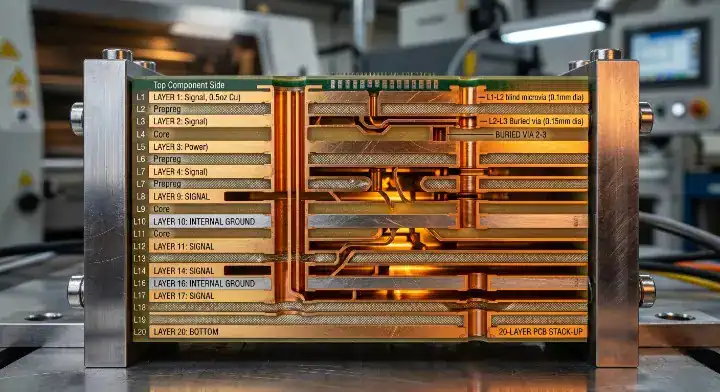
The one fabrication detail that catches less experienced shops is prepreg style matching. I-Tera MT40 is available in 1080, 2116, and 3313 glass styles, each with different resin content and cured Dk. Using 3313 prepreg (63% RC, Dk ~3.30) where 2116 (55% RC, Dk ~3.55) was intended introduces a 7% Dk mismatch that directly shows up as impedance error. On our most recent 20-layer server board using I-Tera MT40 on 12 signal layers, prepreg style validation eliminated a 6% impedance drift that would have required respin.
Bottom line: I-Tera MT40 machines more easily than ultra-low-loss options, but the factory must strictly control spread weave prepreg styles to prevent severe impedance deviations.
9. When Is I-Tera MT40 Overkill and Standard FR-4 Sufficient?
If a board’s maximum signal speed is below 3 Gbps (such as older Gigabit Ethernet, USB 2.0, or simple microcontroller logic), specifying I-Tera MT40 wastes procurement budget. High-Tg FR-4 (like Isola 370HR or FR408HR) handles these sub-3Gbps signals effortlessly. You only pay for I-Tera MT40 when the physics of standard FR-4 cause the signal eye diagram to close completely at the receiver.
Bottom line: Do not specify mid-loss laminates for digital logic designs running below 3 Gbps; stick to reliable, high-Tg FR-4.
10. How Will PCIe Gen6 and 800G Push Designers Beyond I-Tera MT40?
As data centers migrate to PCIe Gen6 (64 GT/s PAM4) and 800G switch architectures, the Nyquist frequencies push past 28 GHz. At these frequencies, a Df of 0.0031 burns through the channel budget too quickly over distances exceeding 10 inches.
At this juncture, designers must shift to ultra-low-loss categories. If environmental mandates also apply, engineering teams will evaluate an EM-892K2 halogen-free M8 laminate for AI servers or TerraGreen 400G2 to hit tighter Df targets. Understanding strict halogen-free PCB specification and manufacturing rules is mandatory, as I-Tera MT40 contains halogens and cannot meet those green compliance directives.
Bottom line: The 64 Gbps PAM4 threshold forces a hardware transition where I-Tera MT40 reaches its physical limit, necessitating an upgrade to materials with a Df of 0.0021 or lower.
11. Frequently Asked Questions
Is I-Tera MT40 good enough for PCIe Gen5 designs? Yes for most designs. PCIe Gen5 runs at 32 GT/s NRZ with Nyquist at 16 GHz. I-Tera MT40 measures approximately 0.84 dB per inch at 16 GHz, which on a typical 8-inch PCIe channel produces 6.7 dB of loss — within the PCIe Gen5 host PCB loss budget. Tachyon 100G saves roughly 1.7 dB of margin on the same channel but costs 50 percent more on material. For PCIe Gen5, the savings typically outweigh the margin gain.
When should I upgrade from I-Tera MT40 to Tachyon 100G? Upgrade when your fastest SerDes exceeds 56 Gbps PAM4 on traces longer than 12 inches, or when your signal integrity simulation shows less than 3 dB of channel margin on I-Tera MT40. PCIe Gen6 at 64 GT/s PAM4 is the transition boundary — I-Tera MT40 passes on short channels but margin shrinks fast beyond 10 inches. For 112 Gbps PAM4 NVLink or 224G PAM4, I-Tera MT40 is not sufficient regardless of trace length.
What makes the I-Tera MT40 RF/MW variant different from the standard version? The RF/MW variant offers four Dk target values — 3.38, 3.45, 3.60, and 3.75 — while maintaining the same Df of 0.0031. No other FR-4-process-compatible laminate provides this Dk flexibility. It allows RF designers to tune impedance, filter response, and electrical length on FR-4 equipment without switching to PTFE. The standard version is fixed at Dk 3.45.
How does I-Tera MT40 compare to Panasonic Megtron 6? Megtron 6 has lower Df at 0.0020 versus I-Tera MT40’s 0.0031, placing it closer to Tachyon 100G performance. Megtron 6 costs roughly 3-5 times FR-4, similar to Tachyon 100G. I-Tera MT40 costs 2-3 times FR-4. Choose I-Tera MT40 when your design can tolerate Df 0.0031 and cost matters. Choose Megtron 6 when you need Df below 0.0025 but are already in the Panasonic supply chain and do not want to pay for Megtron 8.
Is I-Tera MT40 halogen-free? No. I-Tera MT40 is not halogen-free. If your design requires halogen-free compliance, consider TerraGreen 400G2 from Isola (Df 0.0015, halogen-free) or EM-892K2 from EMC (Df approximately 0.0013, halogen-free). Both deliver lower loss than I-Tera MT40 while meeting halogen-free standards, though at higher material cost.
Conclusion
Isola I-Tera MT40 has established itself as the default laminate for PCIe Gen5 and mid-range data center hardware by balancing acceptable high-frequency signal integrity with standard FR-4 processibility. By utilizing hybrid stackups and leveraging its unique RF Dk options, designers can stretch the performance of their hardware while managing BOM costs efficiently. If your team is designing a server, switch, or RF module and needs assistance calculating whether I-Tera MT40 will close your link budget, contact us today to discuss stackup modeling and sample testing.
Written by the QueenEMS Engineering Team
Upload your files today · Free DFM check before production · Ship worldwide
Get your PCB prototypes in as fast as 24 hours. We handle FR4, Rogers, and Flex up to 60 layers — free prototypes for 2–4 layer boards, no minimum order.
Just upload your Gerber + BOM — we source every part, assemble, and inspect (AOI + X‑Ray) so you don't have to chase suppliers. Boards ship in as fast as 24 hours.