
Pushing millimeter-wave designs into mass production requires balancing electrical performance with fabrication reality. This engineering Astra MT77 guide explains how to secure PTFE-level signal integrity while maintaining standard FR-4 shop-floor processing. We will analyze the material’s real-world RF performance up to W-band, detail the cost breakdown against Rogers PTFE alternatives, and outline the exact rules for building complex hybrid stackups alongside high-speed digital laminates for modern 77 GHz radar and 5G communications.
Table of Contents
- What Is Astra MT77 and Why Did Isola Build a Non-PTFE mmWave Laminate?
- What Electrical Properties Make Astra MT77 Stable to W-Band Frequencies?
- How Does Astra MT77 Compare to Tachyon 100G and Megtron 8?
- Which 77 GHz Radar and 5G mmWave Designs Use This Substrate Today?
- How Does the MT77 Family Stack Up Against Rogers RO4350B, RO3003, and RO5880?
- Can You Build an Astra MT77 + Tachyon 100G Hybrid Stackup in One Press?
- What Stackup and Impedance Rules Apply to These RF Boards?
- How Do Fabricators Process This Material Without PTFE Equipment?
- When Should You Still Choose PTFE Over Isola’s mmWave Laminate?
- How Will Material Selection Evolve Toward 6G and Beyond?
What Is Astra MT77 and Why Did Isola Build a Non-PTFE mmWave Laminate?
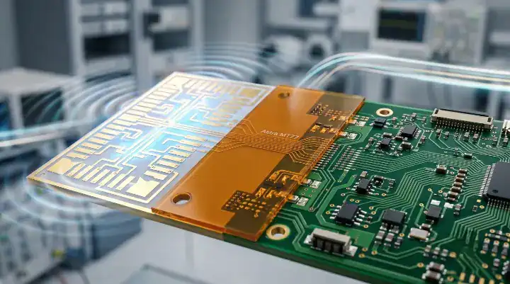
Astra MT77 is Isola’s RF/microwave laminate with Dk 3.00 and Df 0.0017 at 10 GHz, stable to W-band (110 GHz), designed as a drop-in replacement for ceramic-filled PTFE materials on standard FR-4 fabrication equipment. The core engineering value lies in its thermoset glass-reinforced resin base, which eliminates the processing nightmares associated with Teflon-based boards.
Historically, hardware teams designing 77 GHz automotive radars or 28 GHz base station antennas defaulted to PTFE materials like Rogers RO3003 because standard thermosets could not support millimeter-wave frequencies. PTFE delivers excellent signal integrity but introduces severe mechanical instability, requires specialized chemical treatments, and demands dedicated drilling equipment. Isola formulated this thermoset laminate to match PTFE’s wide-temperature Dk stability while allowing fabrication houses to process it exactly like high-Tg FR-4.
Bottom line: This laminate exists to bridge the gap between high-frequency RF performance and high-yield, low-cost commercial PCB fabrication.
What Electrical Properties Make Astra MT77 Stable to W-Band Frequencies?
The material maintains a flat Dk of 3.00 from -40°C to +140°C across frequency bands extending up to 110 GHz (W-band), making it highly predictable for millimeter-wave phase arrays. Its Tg sits at 200°C with a low Z-axis CTE of roughly 45 ppm/°C, ensuring via reliability during multiple thermal cycles.
Per Isola’s official Astra MT77 product documentation, the laminate exhibits a dielectric constant of 3.00 and dissipation factor of 0.0017 at 10 GHz, with Dk stability maintained from -40°C to +140°C across frequencies up to W-band. This temperature stability is critical for automotive radars operating in exposed environments. Furthermore, Astra MT77 conforms to IPC-4103 slash sheets /21 and /26, the standard categories for very low loss RF/microwave laminates.
| Parameter | Value | Test Condition |
|---|---|---|
| Dk | 3.00 | @ 10 GHz / 23°C |
| Df | 0.0017 | @ 10 GHz |
| Dk Temperature Stability | Flat | -40°C to +140°C, W-band |
| Tg | 200°C | DSC |
| Td | 360°C | 5% wt loss |
| CTE X/Y | ~12 ppm/°C | < Tg |
| CTE Z | ~45 ppm/°C | < Tg |
| Peel Strength (HVLP) | ≥ 4.0 lb/in | As received |
| UL 94 | V-0 | Standard |
Bottom line: The combination of a 0.0017 Df and near-zero Dk drift across 180°C of temperature variance allows RF engineers to lock in their antenna geometries without compensating for environmental phase shifts.
How Does Astra MT77 Compare to Tachyon 100G and Megtron 8?
This RF laminate serves as the dedicated microwave sister product to Isola’s Tachyon series, while Megtron 8 operates entirely in the digital domain. While they share similar high-performance positioning, their internal resin chemistries target entirely different signal types.
Engineers specifying the Tachyon 100G high-speed digital laminate specifications know it handles 100+ Gbps PAM4 digital signals with a Df of 0.0021. In contrast, the MT77 formulation drops the Df to 0.0017 and stabilizes the phase response specifically for continuous wave analog RF up to 110 GHz. When evaluating Megtron 8 M8-grade specifications for AI server builds, you are looking at ultra-low loss (Df 0.0010) optimized for long backplane traces, not for exposed millimeter-wave antenna feeds.
It is also important to note environmental compliance. If your project has strict environmental mandates, understanding how to specify halogen-free PCB requirements is necessary because standard MT77 cores contain flame retardants; designers needing a halogen-free RF alternative must pivot to TerraGreen 400G (Df 0.0023).
Bottom line: Use Tachyon 100G or Megtron 8 for digital baseband routing, but transition to this thermoset RF substrate for the analog antenna interfaces.
Which 77 GHz Radar and 5G mmWave Designs Use This Substrate Today?
This substrate currently dominates 77 GHz automotive ADAS radar production and 5G active antenna unit (AAU) manufacturing, having successfully displaced PTFE in Tier-1 supply chains. It is a production-proven material, not a laboratory experiment.
In the automotive sector, radar platforms handling adaptive cruise control, pre-crash sensing, and blind spot detection rely on this material for their front-end antenna arrays. The short trace lengths (typically under 3 inches) mean the slight Df difference versus PTFE is negligible. In telecommunications, 28 GHz and 39 GHz beamforming antennas utilize the laminate for its predictable phase matching across large panel areas. Validating these designs requires finding a partner with verified RF and microwave PCB manufacturing capability to ensure the trace etching meets exact dimensional tolerances.
Bottom line: If you are designing a high-volume 77 GHz radar or a 5G mmWave base station, this laminate is currently the industry default for balancing RF margin with commercial scalability.
How Does the MT77 Family Stack Up Against Rogers RO4350B, RO3003, and RO5880?
The MT77 family delivers Df 0.0017 against RO3003’s 0.0010, offering sufficient performance for 95% of W-band applications while eliminating PTFE processing costs. At frequencies below 28 GHz, it significantly outperforms RO4350B (Df 0.0037).
The cost advantage of Astra MT77 over PTFE materials is not just the laminate price — it is the entire manufacturing chain. On a recent 8-layer 77 GHz radar board, the customer asked us to quote both Astra MT77 and Rogers RO3003 on the two RF layers. Astra MT77 laminate cost ran 45% lower. But the larger savings came from processing: no plasma desmear equipment charge ($800-1,200 per lot on RO3003), no special PTFE drill bits ($35 each vs $8 for standard carbide), no sodium napthalene hole-wall treatment ($400-600 per lot), and no dimensional stability rework on the PTFE layers. Total board cost including all processing came in at approximately 55% of the RO3003 build. For a 500-board production run, that was a savings of roughly $28,000 — meaningful for an automotive Tier-1 supplier optimizing BOM cost on a radar module shipping at 50,000 units per year.
| Material | Manufacturer | Dk @ 10 GHz | Df @ 10 GHz | FR-4 Compatible | Plasma Desmear | Price Tier | Typical Application |
|---|---|---|---|---|---|---|---|
| Astra MT77 | Isola | 3.00 | 0.0017 | ✅ Fully Compatible | ❌ No | Medium | 77GHz radar, 5G, hybrid |
| RO4350B | Rogers | 3.48 | 0.0037 | ✅ Compatible | ❌ No | Med-High | 5G base station |
| RO3003 | Rogers | 3.00 | 0.0010 | ❌ PTFE | ✅ Yes | High | 77GHz radar, satellite |
| RO5880 | Rogers | 2.20 | 0.0009 | ❌ PTFE | ✅ Yes | Very High | mmWave, phased array |
| RT/duroid 5870 | Rogers | 2.33 | 0.0012 | ❌ PTFE | ✅ Yes | Very High | Aerospace radar |
| Tachyon 100G | Isola | 3.02 | 0.0021 | ✅ Compatible | ❌ No | Medium | Digital HSD 100G+ |
Bottom line: RO4350B is sufficient for sub-28 GHz applications, and RO3003 remains necessary for extreme low-loss scenarios, but this Isola substrate occupies the optimal middle ground for high-volume 28-110 GHz designs.
Can You Build an Astra MT77 + Tachyon 100G Hybrid Stackup in One Press?
Yes, combining these two materials in a single lamination cycle is fully supported because their Z-axis coefficients of thermal expansion (CTE) match perfectly at approximately 45 ppm/°C. This hybrid construction places RF processing and high-speed digital logic on the same physical board.
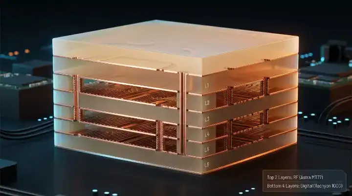
Our most complex Astra MT77 build was a 10-layer hybrid for a 5G mmWave active antenna unit. The stackup combined two Astra MT77 core layers for the 28 GHz beamforming antenna and RF feed network, four Tachyon 100G layers for the eCPRI digital backhaul interface running 25 Gbps NRZ, and four FR408HR layers for power distribution and slow-speed control. CTE matching between Astra MT77 and Tachyon 100G held the board flat after lamination — less than 0.3% bow and twist across the 12-inch × 8-inch panel, within IPC-6012 Class 3 limits. The key learning was prepreg selection: we used Astra MT77 prepreg between the Astra MT77 cores and Tachyon 100G prepreg between the Tachyon cores, avoiding cross-family prepreg mixing that caused impedance drift on an earlier prototype. Insertion loss on the 28 GHz antenna traces measured 0.42 dB/inch on the Astra MT77 stripline layers — within 8% of the customer’s HFSS simulation. Total fab lead time was 5 weeks including 2 weeks for Astra MT77 material allocation. The customer shipped the board into field trial without RF performance issues.
Engineers must specify exact Tachyon 100G processing and HVLP3 copper pairing on the digital layers to prevent signal reflections. Furthermore, this hybrid approach heavily supports HDI PCB fabrication with sequential lamination, allowing microvias to drop from the RF layers directly into the digital processing cores.
Bottom line: While technically mature, fewer than 5% of PCB fabrication houses possess the verified lamination profiles to successfully press an RF and Tachyon hybrid board without warpage or registration failures.
What Stackup and Impedance Rules Apply to These RF Boards?
Impedance control at W-band frequencies requires strictly monitoring copper roughness profiles and prepreg flow characteristics, as variations of just 0.5 mils in trace width can detune a 77 GHz antenna.
Because the Dk of 3.00 is highly consistent, calculating trace widths is straightforward. However, the physical reality of etching dictates the final performance. Hardware teams must account for the HVLP (very low profile) copper utilized on these high-frequency laminates. Standard modeling tools often assume nominal smooth copper, but adding the correct roughness factor (typically Rz ≤ 1.5 µm) into your 3D field solver guarantees that the manufactured board matches your simulation. If you require further assurance on structural design, reviewing our controlled impedance design for RF PCBs provides the baseline calculations necessary before releasing files to fabrication.
Bottom line: Provide your fabricator with the exact target impedance and reference frequency, allowing them to adjust the trace width (usually by ±0.5 mils) to compensate for the specific etch bias of their chemical line.
How Do Fabricators Process This Material Without PTFE Equipment?
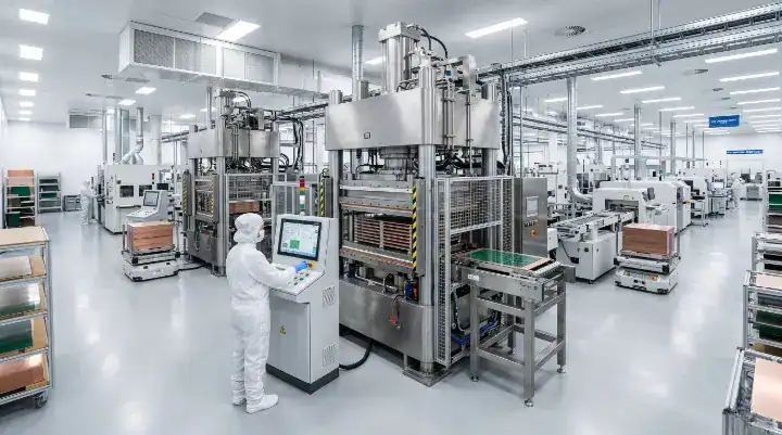
Processing this laminate requires a standard FR-4 hot press cycle operating at 200°C for approximately 60 minutes, bypassing the highly toxic chemical baths and specialized machinery necessary for PTFE production.
The first time our team processed Astra MT77 was for a 77 GHz automotive radar prototype — a 6-layer board with two Astra MT77 core layers carrying the antenna feed network and four standard high-Tg FR-4 layers for power distribution and digital control. The customer’s previous revision used Rogers RO3003 on the RF layers, and the switch to Astra MT77 was driven by cost. Our lamination cycle ran at 200°C for 60 minutes on a standard FR-4 press — identical to what we use for Tachyon 100G. No plasma desmear, no sodium napthalene pre-treatment. Drilling used standard tungsten carbide bits at the same RPM and chipload we run for Tachyon 100G panels, and drill bit life ran roughly 2,200 hits before replacement — compared to the 600-800 hits we typically see on RO3003. Impedance came in at 50 Ω ± 3% on the microstrip RF traces, well within the customer’s ±5% spec. The material cost on the Astra MT77 layers was approximately 45% lower than the equivalent RO3003 build. First-pass yield hit 96% across 30 panels.
Bottom line: If a fabrication house quotes this board using PTFE pricing models or mentions plasma desmear steps, push back immediately; they are misclassifying the material chemistry.
When Should You Still Choose PTFE Over Isola’s mmWave Laminate?
You must retain PTFE materials like Rogers RO3003 or RO5880 when your design relies on extreme low noise figures (NF) at the first-stage low-noise amplifier (LNA) or when trace lengths exceed 6 inches at W-band.
This thermoset substrate adds approximately 0.3 dB per inch of additional loss at 77 GHz compared to RO3003. In short antenna feed structures, this 0.9 dB penalty is easily absorbed by the link budget. However, for deep-space satellite receivers or military phase arrays requiring absolute minimum thermal noise, PTFE is irreplaceable. Additionally, if the antenna geometry requires a dielectric constant strictly below 2.5, RO5880 (Dk 2.20) is required, as the MT77 formulation cannot drop below Dk 3.00.
Bottom line: Default to thermoset materials for 95% of commercial radar and 5G production, but reserve PTFE for edge-case aerospace applications where raw insertion loss overrides fabrication cost.
How Will Material Selection Evolve Toward 6G and Beyond?
As the industry advances toward 6G and combined AI-driven sensor fusion, the line separating pure RF laminates from ultra-high-speed digital substrates will continue to blur, making hybrid stackup compatibility mandatory.
We already see hardware architectures pulling baseband processors directly onto the antenna board. As digital signal rates cross 224 Gbps PAM4, RF engineers will find themselves coordinating directly with the digital SI teams evaluating the next-generation M9 CCL for ultra-low-loss AI server boards. The ability to seamlessly press W-band RF laminates alongside M8 or M9 digital cores without compromising structural integrity will define the next decade of hardware fabrication.
Bottom line: Mastering hybrid material transitions today ensures your engineering team is prepared for the highly integrated RF-to-AI hardware architectures required for 6G deployment.
At QueenEMS, our manufacturing floor regularly processes both pure RF laminates and complex mixed-signal hybrid stackups. Whether you are migrating a 77 GHz radar design away from PTFE or qualifying a new 5G base station, contact us today to schedule a free DFM review of your layer transitions.
Upload your files today · Free DFM check before production · Ship worldwide
Get your PCB prototypes in as fast as 24 hours. We handle FR4, Rogers, and Flex up to 60 layers — free prototypes for 2–4 layer boards, no minimum order.
Just upload your Gerber + BOM — we source every part, assemble, and inspect (AOI + X‑Ray) so you don't have to chase suppliers. Boards ship in as fast as 24 hours.