
Table of Contents
- What Is Rogers RO4350B and Why Is It the RF Industry’s Default Laminate?
- What Electrical and Thermal Properties Define RO4350B?
- Why Does the “Process Dk vs Design Dk” Trap Catch So Many Engineers?
- Which 5G, Radar, and Satellite Applications Use RO4350B Today?
- How Does RO4350B Compare to Isola Astra MT77 Above 28 GHz?
- How Does RO4350B Differ from RO4003C, FR-4, and Megtron Materials?
- How Do You Build a RO4350B + FR-4 Hybrid Stackup Without Warpage?
- When Should You Stay with RO4350B vs Switch to PTFE or Astra MT77?
- How Do Fabricators Process RO4350B on Standard FR-4 Lines?
- How Will 5G mmWave and 77 GHz Radar Shift RO4350B’s Market Position?
- Frequently Asked Questions (FAQ)
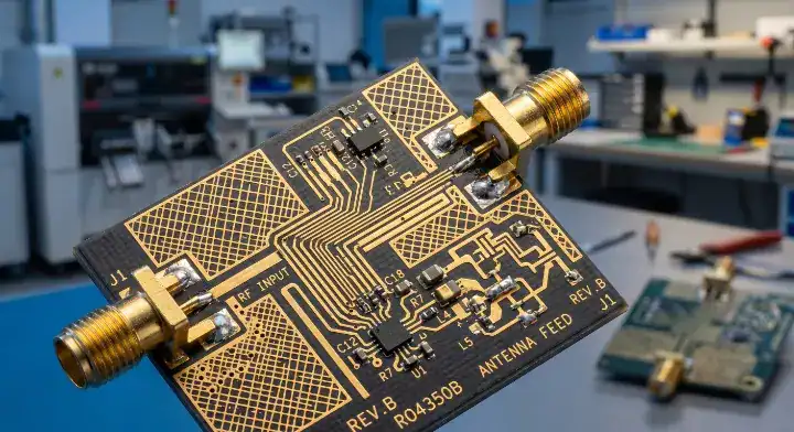
What Is Rogers RO4350B and Why Is It the RF Industry’s Default Laminate?
Rogers RO4350B is a hydrocarbon/ceramic laminate reinforced with woven E-glass, engineered specifically for high-frequency RF and microwave applications. Unlike traditional PTFE (Teflon) materials which require specialized processing and plasma desmear, RO4350B was designed to offer RF-grade electrical performance while maintaining compatibility with standard FR-4 fabrication lines.
This dual advantage—low dielectric loss combined with standard thermoset manufacturability—has made RO4350B the default choice for base station antennas, automotive radar sensors, and 5G sub-6 GHz RF transceivers. It occupies the crucial middle ground in the PCB material spectrum: significantly outperforming standard FR-4 in signal integrity, while avoiding the dimensional instability and high manufacturing costs associated with pure PTFE substrates.
What Electrical and Thermal Properties Define RO4350B?
The baseline specifications of RO4350B define its capability across microwave frequencies. To understand its true operational limits, engineers must evaluate both its nominal datasheet values and its mechanical properties under thermal stress.
| Parameter | Value | Condition |
|---|---|---|
| Dk (Process) | 3.48 ±0.05 | @ 10 GHz, IPC-TM-650 2.5.5.5 stripline |
| Dk (Design / Impedance Modeling) | 3.66 | Rogers recommended for field solver |
| Df (Dissipation Factor) | 0.0037 | @ 10 GHz, stable to 40 GHz+ |
| Tg (Glass Transition Temp) | > 280°C | High thermal stability |
| CTE (Z-axis) | 32 ppm/°C | Highly reliable for plated through-holes |
| CTE (X/Y-axis) | 10-14 ppm/°C | Matched to copper |
| Thermal Conductivity | 0.69 W/mK | ASTM E1952 (~2x higher than standard FR-4) |
| Flammability Rating | V-0 | UL 94 compliance |
| Moisture Absorption | 0.06% | Excellent environmental stability |
| Composition | Hydrocarbon/ceramic + woven E-glass | Non-PTFE |
| Standard Thicknesses | 4, 6.6, 10, 13.3, 16.6, 20, 30, 60 mil | |
| Lead-Free Compatible | YES | Withstands high reflow profiles |
| FR-4 Process Compatible | YES | Core manufacturing advantage |
For further baseline validation, refer to the official Rogers RO4350B product specifications and the primary RO4350B datasheet. The material properties comply heavily with the IPC-4101E standard for rigid boards.
Why Does the “Process Dk vs Design Dk” Trap Catch So Many Engineers?
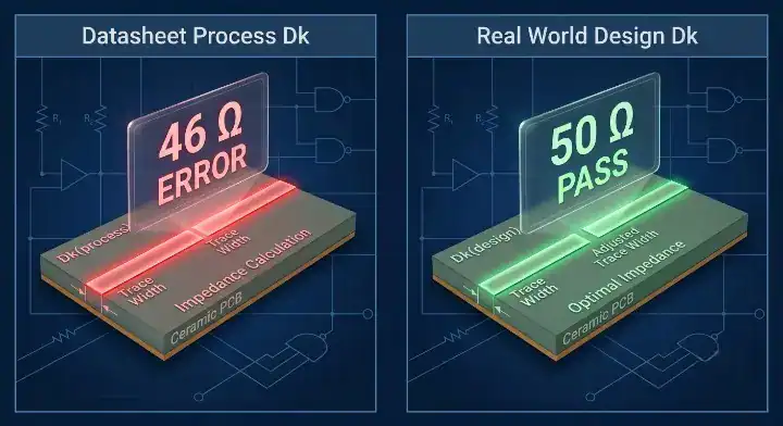
The discrepancy between “Process Dk” and “Design Dk” is the single most frequent cause of RF board spins. Process Dk (3.48) is measured under idealized laboratory conditions using a clamped stripline resonator (IPC-TM-650 2.5.5.5). This method eliminates air gaps and does not account for copper foil roughness. Design Dk (3.66), conversely, is an empirical value recommended by Rogers for use in impedance field solvers (like Polar Si9000), as it factors in the physical realities of the fabricated PCB.
The single most common impedance failure we debug on RO4350B boards traces back to one root cause: the designer modeled to 3.48 Dk. Our internal process Dk on RO4350B using 1 oz LP2 copper at 55% resin content on a 2×1080 construction measures 3.52-3.56 — roughly 2% above the datasheet process Dk and 3% below the recommended design Dk of 3.66. On a 10 mil, 50 Ω microstrip, that 2% Dk shift translates to approximately 1.5-2.0 Ω impedance error — manageable within ±5% tolerance. But when a designer uses 3.48 instead of our process Dk of 3.54, the error compounds to 4-5 Ω — enough to push a 50 Ω trace to 46 Ω, which is outside Class 3 tolerance on the first article. We now require every RO4350B design review to start with one question: “what Dk value did you use in your impedance model?” If the answer is 3.48, we recalculate before cutting tooling. This single step has eliminated 80% of our RO4350B impedance escapes.
To prevent these discrepancies, always consult a controlled impedance design and manufacturing guide and explicitly request your fabricator’s construction-specific Dk.
Which 5G, Radar, and Satellite Applications Use RO4350B Today?
RO4350B covers approximately 80% of current high-frequency infrastructure requirements. The material is the established industry standard for sub-6 GHz 5G macro-cell antennas, 24 GHz industrial radar modules, and point-to-point microwave backhauls.
Because of its relatively high thermal conductivity (0.69 W/mK), it is exceptionally well-suited for Power Amplifier (PA) modules and active antenna arrays that generate substantial localized heat. For teams evaluating these applications, verifying material limits through professional RF and high-frequency PCB manufacturing services ensures that localized thermal management does not compromise signal loss margins. However, as operating frequencies transition from 24 GHz up to 40 GHz and 77 GHz mmWave bands, standard RO4350B begins to approach its absolute insertion loss limit.
How Does RO4350B Compare to Isola Astra MT77 Above 28 GHz?
When engineers push designs beyond 28 GHz, the primary competitor to RO4350B is Isola Astra MT77. While RO4350B maintains dominance at lower frequencies due to manufacturing maturity, Astra MT77 offers a fundamentally lower loss profile for mmWave applications.
| Feature | Rogers RO4350B | Isola Astra MT77 |
|---|---|---|
| Dk @ 10 GHz | 3.48 (process) / 3.66 (design) | 3.00 |
| Df @ 10 GHz | 0.0037 | 0.0017 |
| Df @ 28 GHz | ~0.004 | ~0.0018 |
| Tg | > 280°C | 200°C |
| Thermal Conductivity | 0.69 W/mK | ~0.40 W/mK |
| Insertion Loss @ 10 GHz | ~0.18 dB/inch (microstrip) | ~0.12 dB/inch |
| Insertion Loss @ 28 GHz | ~0.45-0.50 dB/inch | ~0.30-0.35 dB/inch |
| Composition | Hydrocarbon/ceramic | Thermoset resin |
| 77 GHz Radar Target | ⚠️ Borderline (Requires VF variant) | ✅ Native design target |
| Primary Advantage | Thermal conductivity & legacy trust | Lower Df & lower insertion loss |
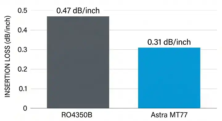
Last year we ran a head-to-head comparison build for a customer designing a 28 GHz 5G small cell radio — identical 6-layer stackup, one set on RO4350B and one set on Astra MT77, both with LP2 copper on the RF layers. Insertion loss at 28 GHz on the RO4350B microstrip feed measured 0.47 dB/inch; on the Astra MT77 build, 0.31 dB/inch — a 34% improvement. Over the customer’s 4-inch antenna feed network, that translated to 0.64 dB of additional margin on the Astra MT77 boards. Impedance accuracy was comparable: both held 50 Ω ±3% after process Dk correction. The cost difference was interesting — RO4350B material ran approximately 15% more expensive than Astra MT77 on a per-panel basis because Rogers pricing carries a brand premium that Isola does not. Total board cost including processing was within 5% between the two. The customer switched to Astra MT77 for production. The deciding factor was not the 0.64 dB loss advantage — it was the 15% material savings at equivalent or better performance. You can verify the Isola properties via Isola Astra MT77 official data.
How Does RO4350B Differ from RO4003C, FR-4, and Megtron Materials?
Navigating the material selection matrix requires understanding how RO4350B sits relative to other industry staples.
Below is a direct comparison between RO4350B and its sister material, RO4003C:
| Dimension | Rogers RO4350B | Rogers RO4003C |
|---|---|---|
| Dk | 3.48 | 3.38 |
| Df | 0.0037 | 0.0027 |
| UL 94 | V-0 (Flame Retardant) | Not rated |
| Price Tier | Slightly higher | Slightly lower |
| Selection Logic | Requires UL certification → RO4350B | No UL required, pursuing lower Df → RO4003C |
vs RO4003C: As shown above, the critical distinction is the UL 94 rating. RO4350B is formulated with brominated fire retardants to achieve a UL 94 V-0 rating. RO4003C does not contain these retardants, meaning it offers a slightly lower Df but lacks a UL rating. If your end product requires UL certification, you must use RO4350B.
vs FR-4: RO4350B operates with roughly 4 times lower dielectric loss than FR-4. While reviewing standard FR-4 material properties and Tg grades makes sense for digital control layers, standard FR-4 fails completely in RF signal integrity above 2 GHz.
vs Megtron: RO4350B is an RF material. If your design is entirely high-speed digital (HSD) rather than RF, materials like Megtron are more appropriate. For example, 100Gbps switch architectures and AI hardware rely heavily on Megtron 8 M8-grade specifications for AI server builds due to their extreme low Dk/Df tailored for digital differential pairs, rather than RF microstrips.
How Do You Build a RO4350B + FR-4 Hybrid Stackup Without Warpage?
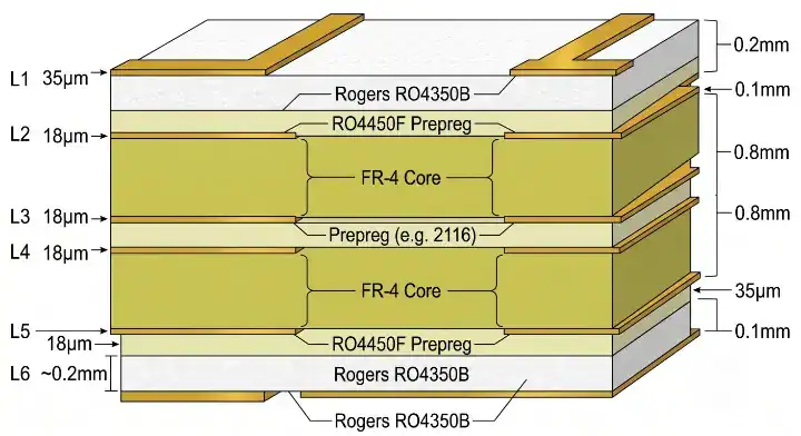
To control costs, most multilayer RF boards utilize a hybrid stackup: high-frequency signals route on the outer RO4350B layers, while power, ground, and digital logic route on inner FR-4 layers. The primary manufacturing challenge here is managing the Coefficient of Thermal Expansion (CTE) mismatch between the disparate materials during lamination.
Our most common RO4350B build pattern is a 6-layer RF hybrid: two RO4350B core layers on the RF signal side (microstrip + ground), bonded with RO4450F prepreg to four FR-4 layers carrying digital control, power distribution, and IF routing. The critical fabrication detail is stackup symmetry — RO4350B on top and bottom with FR-4 in the center, ensuring balanced CTE expansion during lamination. On a recent 5G small cell board, an asymmetric first-article design placed all RO4350B on layers 1-2 with FR-4 on layers 3-6. The result was 0.8% bow after lamination — above the IPC-6012 Class 3 limit of 0.75%. We rebuilt with RO4350B on layers 1-2 and 5-6 (symmetric), FR-4 on layers 3-4 (center), and bow dropped to 0.3%. Material cost on the symmetric build was identical; the only change was the stackup arrangement. For designs requiring more than 6 layers of RF content, we recommend I-Tera MT40 on the secondary layers instead of FR-4 for better CTE matching with RO4350B.
For hybrid architectures that mix RF and extreme high-speed digital logic, some engineers cross-reference the Tachyon 100G high-speed digital laminate guide to pair RO4350B with ultra-low loss digital cores instead of FR-4.
When Should You Stay with RO4350B vs Switch to PTFE or Astra MT77?
Material selection should be strictly driven by frequency bounds and thermal requirements. Over-specifying to PTFE when RO4350B suffices only inflates fabrication costs.
| Application / Frequency Bound | RO4350B Status | Astra MT77 | PTFE (RO3003/5880) | I-Tera MT40 |
|---|---|---|---|---|
| < 6 GHz (Sub-6 5G, WiFi 6) | ✅ Default Choice | Overspec | Overspec | ✅ Adequate |
| 6-28 GHz (24GHz Radar, 5G FR2) | ✅ Mainstream | ✅ Viable Alternative | Not Required | ⚠️ Borderline |
| 28-40 GHz (5G mmWave) | ⚠️ Borderline Limit | ✅ Primary Choice | ✅ Viable | ❌ Fails |
| 40-77 GHz (V2X, Auto Radar) | ❌ Standard Fails | ✅ Primary Choice | ✅ Viable | ❌ Fails |
| 77-110 GHz (W-band Imaging) | ❌ Fails | ✅ Viable to W-band | ✅ Primary Choice | ❌ Fails |
| Power Amplifiers (High Heat) | ✅ Primary (0.69 W/mK) | ⚠️ Marginal (0.40 W/mK) | ✅ Viable | ❌ Fails |
How Do Fabricators Process RO4350B on Standard FR-4 Lines?
The core appeal of RO4350B from a fabrication standpoint is its compatibility with thermoset processing parameters. Unlike pure PTFE, RO4350B does not require sodium naphthalene etching or plasma desmear prior to plated through-hole (PTH) metallization. Standard carbide drill bits operate efficiently, though tool life is slightly reduced compared to FR-4 due to the ceramic filler.
Because the material uses conventional lamination cycles, fabricators can process RO4350B panels rapidly. However, buyers should note that lead times for raw RO4350B laminates often require an additional 5-10 days to procure if the specific thickness is not held in fab inventory. Furthermore, for eco-conscious designs, it is important to note that due to its brominated flame retardants, RO4350B does not meet the strict definitions outlined in a standard halogen-free PCB specification guide.
How Will 5G mmWave and 77 GHz Radar Shift RO4350B’s Market Position?
RO4350B will remain the undisputed backbone of the RF PCB industry for frequencies up to 28 GHz. Its unique combination of excellent thermal conductivity, rigid mechanical stability, and predictable FR-4-like processing makes it indispensable for sub-6 GHz infrastructure and high-power RF amplifier circuits.
However, as automotive platforms transition heavily to 77 GHz radar and satellite systems push deep into the Ka-band and V-band, the insertion loss of standard RO4350B becomes a bottleneck. In these >40 GHz segments, Isola Astra MT77 and pure PTFE laminates will capture the growth. By understanding exactly where RO4350B excels—and where its physical boundaries lie—engineers can specify stackups that balance extreme RF performance with commercial manufacturing viability.
Frequently Asked Questions (FAQ)
Why does my RO4350B impedance not match simulation?
Most likely because you modeled to the datasheet process Dk of 3.48 instead of the design Dk of 3.66 or your fabricator’s actual process Dk (typically 3.41-3.55). A 2-3 percent Dk error translates to 4-7 ohms of impedance shift on a 50 ohm microstrip. Always request your fabricator’s measured process Dk for the specific RO4350B construction before finalizing trace widths.
Should I use RO4350B or Astra MT77 for 28 GHz 5G designs?
It depends on the circuit function. For antenna feed networks and passive RF circuits at 28 GHz, Astra MT77 delivers 34 percent lower insertion loss at 0.31 dB per inch versus RO4350B at 0.47 dB per inch. For power amplifier stages where thermal conductivity matters, RO4350B’s 0.69 W/mK outperforms Astra MT77’s 0.40 W/mK. Below 10 GHz, RO4350B is the clear default. Above 40 GHz, Astra MT77 wins on loss performance.
Does RO4350B need plasma desmear or special processing?
No. RO4350B processes on standard FR-4 fabrication lines without plasma desmear, special drill bits, or PTFE-specific treatments. Standard carbide drill bits, conventional etching, and typical lamination parameters work without modification. This is RO4350B’s primary advantage over PTFE materials like RO3003 or RT/duroid 5880.
How do I prevent warpage in a RO4350B + FR-4 hybrid stackup?
Build a symmetric stackup — distribute RO4350B layers equally on top and bottom with FR-4 in the center. Use RO4450F prepreg for bonding. Asymmetric placement of all RO4350B on one side causes bow exceeding 0.75 percent after lamination. For boards with more than 6 RF layers, substitute I-Tera MT40 for FR-4 on non-RF layers for better CTE matching.
When should I switch from RO4350B to PTFE materials?
Switch to PTFE when your application requires Df below 0.001 at frequencies above 40 GHz — specifically 77 GHz automotive radar LNA front ends, Ka-band satellite low-noise blocks, and W-band imaging systems. For everything between 28 GHz and 77 GHz where PTFE processing is undesirable, Isola Astra MT77 serves as a non-PTFE alternative with Df 0.0017 — roughly half of RO4350B’s loss.
If your team is finalizing an impedance model for a hybrid RF architecture, contact us today to verify your process Dk and stackup symmetry before releasing Gerbers.
Written by the QueenEMS Engineering Team
Upload your files today · Free DFM check before production · Ship worldwide
Get your PCB prototypes in as fast as 24 hours. We handle FR4, Rogers, and Flex up to 60 layers — free prototypes for 2–4 layer boards, no minimum order.
Just upload your Gerber + BOM — we source every part, assemble, and inspect (AOI + X‑Ray) so you don't have to chase suppliers. Boards ship in as fast as 24 hours.