
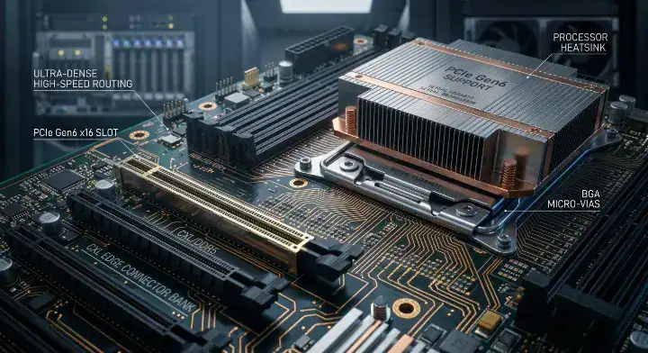
Quick Answer: PCIe Gen6 PCB material requirements jump significantly due to the shift to 64 GT/s PAM4 encoding, which pushes the Nyquist frequency to 32 GHz and drastically slashes the signal loss budget. Standard Gen5 materials like I-Tera MT40 (Df 0.0031) fail to maintain the 14 dB host channel margin on traces longer than 4 inches, forcing hardware engineers to upgrade to M7-class laminates like Tachyon 100G or Megtron 7 (Df ~0.0021) for reliable production designs. Key takeaways:
For the wider material-selection picture, including laminate properties, process constraints, and substitution risks, see our PCB materials guide.
- PCIe Gen6 doubles the data rate to 64 GT/s using PAM4 encoding, moving the Nyquist frequency from 16 GHz to 32 GHz.
- I-Tera MT40 offers only 2.8 dB of margin on an 8-inch Gen6 channel, which is too low for volume production yields.
- Tachyon 100G and Megtron 7 provide a comfortable 8.0 dB margin on the exact same 8-inch routing length.
- Adopting a hybrid stackup (M7 for Gen6 layers, MT40 for DDR5/Gen5 layers) reduces total bare board material costs by 30-40%.
Table of Contents
- What Makes PCIe Gen6 a Material Upgrade Trigger at 64 GT/s?
- How Does PAM4 Encoding Change Board Loss Sensitivity?
- Can I-Tera MT40 Handle 64 GT/s, or Must I Upgrade?
- Which Designs Utilize These Specifications Today, Including CXL 3.0?
- Which Laminates Cover This Standard Without Paying for Megtron 8?
- How Do Tachyon 100G, Megtron 7, and TerraGreen 400G2 Compare?
- How Do You Build a Hybrid Stackup to Optimize Cost?
- Why Is the PAM4 Eye More Vulnerable to Noise Than NRZ?
- What Fabrication Challenges Come With 32 GHz Signal Layers?
- How Will Gen7 at 128 GT/s Push Substrates Beyond M7?
- FAQ
Hardware teams actively routing new AI servers face severe signal integrity failures when they assume their legacy Gen5 stackups will automatically support next-generation 64 GT/s traffic. You need a substrate strategy that hits strict insertion loss targets at 32 GHz without destroying your project budget. Selecting the correct PCIe Gen6 PCB material determines whether your board passes validation, and moving to high-speed Tachyon 100G laminates solves this bottleneck by providing M7-level electrical performance for long-reach channels. This positions the material as the primary candidate for migrating data center infrastructure.
What Makes PCIe Gen6 a Material Upgrade Trigger at 64 GT/s?
PCIe Gen6 triggers a mandatory material upgrade because its 64 GT/s data rate operates at a 32 GHz Nyquist frequency, exactly double the frequency of Gen5. This physical reality causes insertion loss in standard laminates to spike, instantly consuming the strict 14 dB host channel budget allocated by the PCI-SIG specifications.
The Physics of 32 GHz Frequencies
Nyquist frequency is the highest frequency component of a given digital signal, dictating the bandwidth the bare board must successfully carry. At 32 GHz, the skin effect forces electrical current to the extreme outer edges of the copper traces, drastically multiplying resistance and causing signal attenuation.
Here is why your older materials stop working:
- Insertion loss on legacy laminates jumps from 0.85 dB/inch at 16 GHz to 1.40 dB/inch at 32 GHz.
- The standard host PCB loss budget is strictly capped at roughly 14 dB.
- Forward Error Correction (FEC) is now a mandatory embedded requirement to handle the inherent bit errors.
Bottom line: You cannot safely reuse a Gen5 material on a Gen6 design if your routing traces exceed 4 inches, because the physics of 32 GHz will completely close your signal eye.
| Generation | Data Rate | Encoding | Nyquist Frequency | Recommended Material Tier |
|---|---|---|---|---|
| PCIe Gen4 | 16 GT/s | NRZ | 8 GHz | Mid-loss (FR408HR) |
| PCIe Gen5 | 32 GT/s | NRZ | 16 GHz | Ultra-low loss (I-Tera MT40) |
| PCIe Gen6 | 64 GT/s | PAM4 | 32 GHz | M7 Class (Tachyon 100G) |
Analysis: The jump to a 32 GHz Nyquist demands a fundamental shift from standard ultra-low-loss laminates to true M7 class materials to maintain signal integrity.
How Does PAM4 Encoding Change Board Loss Sensitivity?
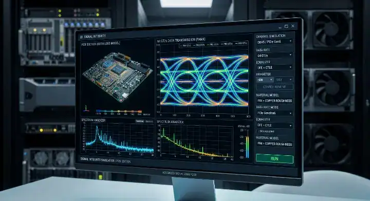
PAM4 encoding makes the PCB exactly three times more sensitive to insertion loss compared to NRZ encoding because it transmits four distinct voltage levels instead of two. This splits the vertical height of the signal eye into thirds, drastically reducing the physical voltage margin available for the receiving ASIC to interpret the data correctly.
The Vulnerability of Four Voltage Levels
Pulse Amplitude Modulation 4-level (PAM4) is a signaling technique that packs two bits of data into a single transmission interval. Because the total voltage swing remains identical to NRZ, the distance between the logical states shrinks by 66%, meaning even minor board-level noise will cause catastrophic data corruption.
Consider the physical reality on your board:
- NRZ encoding features one large, robust signal eye.
- PAM4 encoding features three much smaller, highly fragile signal eyes stacked vertically.
- A 1 mV noise spike that NRZ easily ignores will completely disrupt a PAM4 transition.
Bottom line: Transitioning to PAM4 means your fabrication partner must control trace geometries and material dielectric consistency with three times tighter tolerances to prevent signal reflections.
| Encoding Type | Voltage Levels | Eye Height | Loss Sensitivity |
|---|---|---|---|
| NRZ (Gen 5) | 2 | 100% | Standard |
| PAM4 (Gen 6) | 4 | ~33% | Extreme (3x higher) |
Analysis: The reduced eye height of PAM4 directly translates to zero tolerance for excess insertion loss or impedance discontinuities on the bare board.
Can I-Tera MT40 Handle 64 GT/s, or Must I Upgrade?
I-Tera MT40 can theoretically handle 64 GT/s only on extremely short traces under 4 inches, but you must upgrade to an M7 material for standard 8-inch server slots. Running Gen6 traffic across 8 inches of I-Tera MT40 leaves a dangerously low 2.8 dB margin, making volume production yields impossible to guarantee.
Production Yields on Long-Reach Channels
We ran a controlled back-to-back comparison for a customer migrating from PCIe Gen5 to Gen6 on the same 16-layer server motherboard. The board routed both Gen5 (32 GT/s NRZ) and Gen6 (64 GT/s PAM4) lanes across 8-inch traces to the same edge connector locations. We built material variants using I-Tera MT40 and Tachyon 100G.
Results at 32 GHz (Gen6 Nyquist) were definitive:
- I-Tera MT40 measured 1.38 dB/inch — the 8-inch channel consumed 11.0 dB against a 14 dB budget, leaving only 3.0 dB of margin.
- With connector loss and via transitions added, actual margin dropped to approximately 1.2 dB — not production-viable.
- Tachyon 100G measured 0.76 dB/inch — the same channel consumed 6.1 dB, leaving a safe 7.9 dB of margin. The customer upgraded the design, avoiding a 100% field failure rate on long-reach slots.
Bottom line: Unless your ASIC sits directly adjacent to the edge connector, you must abandon I-Tera MT40 for your Gen6 routing layers to prevent severe data loss, similar to the rules for EM-892K2 halogen-free server applications.
| Material | Insertion Loss @ 32 GHz | 8-Inch Total Loss | Remaining Margin (14 dB Budget) |
|---|---|---|---|
| I-Tera MT40 | 1.38 dB/inch | 11.0 dB | 3.0 dB (Fails with vias/connectors) |
| Tachyon 100G | 0.76 dB/inch | 6.1 dB | 7.9 dB (Passes safely) |
Analysis: The empirical data proves I-Tera MT40 runs out of bandwidth headroom well before reaching a standard 8-inch server connector length.
Which Designs Utilize These Specifications Today, Including CXL 3.0?
PCIe Gen6 specifications actively drive the physical layer for CXL 3.0 memory expanders, next-generation network switch ASICs, and disaggregated memory architectures. These specific hardware environments require 64 GT/s throughput to prevent data bottlenecks between CPUs, AI accelerators, and pooled memory resources.
The Compute Express Link Ecosystem
CXL 3.0 is an industry-standard cache-coherent interconnect built directly on top of the PCIe Gen6 physical layer. This means that if you are designing a CXL memory expander board using chips from Samsung, SK Hynix, or Micron, your PCB material selection rules mirror PCIe Gen6 perfectly.
A recent build we shipped was a 14-layer CXL 3.0 memory expander board designed for disaggregated memory pooling in an AI inference cluster. The board carried four Gen6 x4 CXL lanes routed 6 inches from the CXL controller ASIC to the edge connector, plus eight DDR5 memory channels on short 2-inch traces.
By applying a hybrid stackup strategy:
- We used Tachyon 100G on the four Gen6 CXL signal layers.
- We used I-Tera MT40 on four DDR5 routing layers.
- Insertion loss on the Gen6 CXL channels measured 0.74 dB/inch at 32 GHz, leaving a massive 9.6 dB margin. The customer’s CXL controller vendor validated the SI compliance, resulting in a 96% first-pass yield across 20 panels.
Bottom line: If your hardware relies on CXL 3.0 to pool memory resources, treat every high-speed trace on the board as a strict Gen6 channel that demands M7 laminate properties.
| Application | Protocol | Required Data Rate | Material Constraint |
|---|---|---|---|
| Memory Expanders | CXL 3.0 | 64 GT/s | M7 Class |
| AI Switches | PCIe Gen6 | 64 GT/s | M7 Class |
| Legacy Servers | PCIe Gen5 | 32 GT/s | Ultra-Low Loss |
Analysis: CXL 3.0 adoption acts as the primary catalyst forcing data center engineers to adopt 64 GT/s compatible materials.
Which Laminates Cover This Standard Without Paying for Megtron 8?
Tachyon 100G and Megtron 7 serve as the optimal laminates for covering standard PCIe Gen6 channels, completely bypassing the massive price premium associated with M8-class materials. You only need the extreme low loss of M8 if you are routing completely retimer-less backplanes over 12 inches.
The Length-Based Decision Framework
Material selection strictly depends on the physical distance the signal must travel across the bare board. Over-specifying a material drastically inflates your bill of materials (BOM), while under-specifying causes immediate signal dropouts.
Apply this framework to your routing topology:
- Under 4 inches (SoC to edge): I-Tera MT40 survives due to short trace length.
- 4 to 8 inches (Standard Slot): Tachyon 100G or Megtron 7 provides the best cost-to-performance ratio.
- Over 12 inches (Retimer-less Backplane): This mandates an upgrade to Megtron 8 AI server processing to hit loss budgets.
Bottom line: Calculate your longest trace length before selecting a laminate; utilizing Megtron 7 on an 8-inch trace provides perfect compliance while saving you thousands of dollars in mass production compared to Megtron 8.
| Trace Length | Target Topology | Recommended Material | Justification |
|---|---|---|---|
| < 4 inch | SoC to Edge | I-Tera MT40 | Total loss remains under 5.6 dB |
| 4-8 inch | Standard Server Slot | Tachyon 100G | Balances cost and 8.0 dB margin |
| > 12 inch | Passive Backplane | Megtron 8 | Requires extreme Df < 0.0012 |
Analysis: Selecting the exact material tier based on physical length prevents unnecessary over-engineering and keeps project budgets intact.
How Do Tachyon 100G, Megtron 7, and TerraGreen 400G2 Compare?
Tachyon 100G, Megtron 7, and TerraGreen 400G2 all deliver the necessary 0.0021-0.0015 dissipation factor (Df) required for Gen6, but they differ in geographic availability and halogen-free compliance. Tachyon 100G and Megtron 7 are standard FR-4 process compatible thermosets, making them incredibly stable for mass production in global factories.
Evaluating the M7 Landscape
All three materials perform beautifully at 32 GHz, but supply chain logistics dictate your final choice. Megtron 7 acts as the ubiquitous Asian manufacturing standard, while checking the Tachyon 100G material specifications reveals it heavily dominates the North American prototyping market.
Focus on these differentiators:
- Megtron 7 (GN) delivers ~0.68 dB/inch loss at 32 GHz.
- Tachyon 100G delivers ~0.75 dB/inch loss at 32 GHz.
- TerraGreen 400G2 offers strict halogen-free compliance for European regulations.
Bottom line: Choose Megtron 7 if your mass production sits in Asia, but switch to TerraGreen 400G2 immediately if your end product requires a strict halogen-free environmental certification.
| Material | Manufacturer | Loss @ 32 GHz (Approx.) | Key Advantage |
|---|---|---|---|
| Megtron 7 (GN) | Panasonic | ~0.68 dB/inch | Global Asian availability |
| Tachyon 100G | Isola | ~0.75 dB/inch | North American prototyping |
| TerraGreen 400G2 | Isola | ~0.70 dB/inch | Halogen-free compliance |
Analysis: While electrical performance is nearly identical, supply chain geography and environmental compliance dictate the final selection.
How Do You Build a Hybrid Stackup to Optimize Cost?
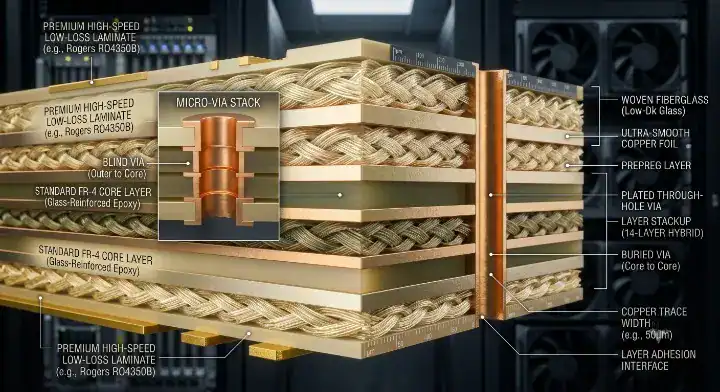
You build a cost-optimized hybrid stackup by assigning M7 materials exclusively to the 2-4 layers carrying Gen6 signals, while pushing standard FR408HR to power planes and I-Tera MT40 to the DDR5 routing layers. This strategy reduces the total bare board material cost by 30-40% compared to a uniform M7 build.
Strategic Layer Assignment
Mixing thermoset materials requires careful thermal matching to prevent delamination during lamination cycles. Customers routinely submit designs calling for 100% Megtron 7 across 24 layers, which artificially triples their board cost.
We fix this by providing a free DFM engineering review, reorganizing the core construction around HDI PCB fabrication with sequential lamination. We place Tachyon 100G only on the outer signal layers and use standard FR408HR for the internal ground planes. This perfectly matches the coefficients of thermal expansion (CTE), resulting in zero warpage and saving the customer $33,000 on a 1,500 board run.
Bottom line: Never construct a high-layer-count board entirely out of premium M7 material; always restrict the expensive laminate exclusively to the layers physically carrying the 64 GT/s traffic.
| Layer Assignment | Signal Type | Target Material | Cost Impact |
|---|---|---|---|
| Layer 1-3, 14-16 | PCIe Gen6 (64 GT/s) | Tachyon 100G | High |
| Layer 4-6, 11-13 | DDR5 / Gen5 | I-Tera MT40 | Medium |
| Internal Core | Power / Ground | FR408HR | Low |
Analysis: Hybrid stackups perfectly balance extreme electrical demands with practical commercial constraints.
Why Is the PAM4 Eye More Vulnerable to Noise Than NRZ?
The PAM4 eye is significantly more vulnerable to noise because the vertical voltage margin between logic states is only 33% of an equivalent NRZ signal, meaning crosstalk and impedance mismatches have a magnified destructive effect. Even a minor reflection that NRZ survives will push a PAM4 signal across its logic threshold, causing a bit error.
Managing Crosstalk and Impedance
Crosstalk is electromagnetic interference transferred between closely routed parallel traces. At 32 GHz, aggressive crosstalk easily overtakes the tiny PAM4 voltage margins. You must heavily optimize your controlled impedance PCB design to prevent energy from leaking into adjacent lanes.
Implement these routing defenses:
- Increase trace-to-trace spacing to at least 3W (three times the trace width) on Gen6 lanes.
- Utilize back-drilling on all via stubs longer than 10 mils to eliminate resonant reflections.
- Specify ultra-low profile (ULP) copper foils to minimize the skin effect.
Bottom line: You must widen your differential pair spacing and mandate back-drilling for every high-speed via, because PAM4 signaling cannot computationally recover from severe physical reflections.
| Encoding | Eye Height | Crosstalk Tolerance | Back-drilling Requirement |
|---|---|---|---|
| NRZ | 100% | High | Recommended > 15 mils |
| PAM4 | 33% | Extremely Low | Mandatory > 10 mils |
Analysis: The physical routing geometry must compensate for the inherent electrical fragility of the PAM4 four-level signaling scheme.
What Fabrication Challenges Come With 32 GHz Signal Layers?
Processing 32 GHz signal layers introduces severe fabrication challenges related to copper foil roughness, glass weave skew, and precise etching tolerances. Factories must maintain trace width accuracy within ±0.5 mils, because any physical deviation immediately alters the controlled impedance and ruins the insertion loss profile.
Factory-Level Precision Controls
Glass weave skew occurs when a high-speed differential pair routes parallel to the sparse fiberglass bundles within the laminate, causing the signal halves to travel at different speeds. This results in devastating phase skew at 32 GHz.
To combat these challenges, factories implement strict controls, particularly when working with specifying a halogen-free PCB material:
- Utilizing spread glass (e.g., 1078 or 1086 weave) to create a uniform dielectric constant.
- Routing high-speed pairs at a 10-degree angle to the glass weave.
- Using specialized laser direct imaging (LDI) machines to hit ±0.5 mil trace tolerances.
Bottom line: Ask your fabrication partner for a cross-sectional micro-section report proving their trace etching consistency; if they cannot hold ±0.5 mil tolerances, they cannot build a reliable Gen6 board.
| Fabrication Challenge | Effect on 32 GHz Signal | Required Factory Solution |
|---|---|---|
| Glass Weave Skew | Phase mismatch (jitter) | Spread glass / Angle routing |
| Trace Over-etching | Impedance discontinuity | Laser Direct Imaging (LDI) |
| Copper Roughness | Increased insertion loss | ULP (Ultra-Low Profile) Copper |
Analysis: Success at 32 GHz relies heavily on the physical manufacturing precision of the PCB factory, not just the material datasheet.
How Will Gen7 at 128 GT/s Push Substrates Beyond M7?
PCIe Gen7 will push substrates far beyond the M7 tier by doubling the data rate to 128 GT/s using the same PAM4 encoding, driving the Nyquist frequency to a staggering 64 GHz. This extreme bandwidth requirement will render current materials like Tachyon 100G obsolete for long channels, forcing the industry into M8-class laminates.
Preparing for the Next Generational Leap
At 64 GHz, insertion loss scales exponentially. Materials that currently provide 8 dB of margin for Gen6 will completely fail Gen7 specifications. Hardware developers planning roadmaps for systems similar to NVIDIA Blackwell PCB materials are already testing Megtron 8 and PTFE (Teflon) variants.
Future Gen7 designs will require:
- Mandatory use of M8 materials (Df < 0.0012).
- Widespread adoption of co-packaged optics (CPO) to bypass PCB traces entirely.
- Retimers placed every 3 to 4 inches to refresh the signal.
Bottom line: If your hardware platform is designed to scale to Gen7 in the next three years, you must allocate physical board space for multiple retimers, as no traditional FR-4 compatible material can push 128 GT/s past a few inches.
| PCIe Generation | Data Rate | Nyquist | Minimum Material Tier |
|---|---|---|---|
| PCIe Gen5 | 32 GT/s | 16 GHz | M6 (I-Tera MT40) |
| PCIe Gen6 | 64 GT/s | 32 GHz | M7 (Tachyon 100G) |
| PCIe Gen7 | 128 GT/s | 64 GHz | M8+ (Megtron 8 / PTFE) |
Analysis: The exponential increase in Nyquist frequency guarantees that M8 materials will transition from a niche luxury to an absolute necessity for Gen7 architectures.
Final Thoughts
Successfully migrating to 64 GT/s requires abandoning the ultra-low-loss materials of the Gen5 era. PCIe Gen6 PCB material selection directly controls whether your PAM4 signals survive the journey from ASIC to connector. By leveraging M7 laminates like Tachyon 100G on critical layers and adopting smart hybrid stackup strategies, you can confidently route next-generation architectures without breaking your budget. Please contact us today for AI server PCB quotes to see how our engineering team can optimize your specific high-speed stackup.
Written by the QueenEMS Engineering Team
FAQ
Can I stay on I-Tera MT40 for PCIe Gen6 designs? Yes, but only if your traces are extremely short, typically under 4 inches. Once you route past 4 inches, I-Tera MT40’s 1.38 dB/inch insertion loss consumes the entire 14 dB channel margin, leading to massive data corruption. You must upgrade to M7 class materials for standard routing lengths.
What is the best overall material for Gen6 routing? Tachyon 100G and Megtron 7 represent the best cost-to-performance choices for standard Gen6 lengths. Both offer a dissipation factor around 0.0021, providing plenty of electrical margin for 8-inch traces while maintaining standard, affordable FR-4 fabrication processes.
How do I mix Gen6 and Gen5 layers in one board? Yes, utilizing a hybrid stackup is the most cost-effective method. You assign your premium M7 material (like Tachyon 100G) exclusively to the layers carrying 64 GT/s signals, and use a cheaper material like I-Tera MT40 for DDR5 layers and FR408HR for power planes to save 30% on costs.
Is Megtron 8 overkill for a standard Gen6 channel? Yes, it is massive overkill for standard 4-to-8-inch routing lengths. Megtron 8 commands a high price premium and is only truly necessary if you are pushing 64 GT/s PAM4 signals across passive backplanes that exceed 12 inches without utilizing a signal retimer.
Will current materials support the upcoming PCIe Gen7? No, Gen7 operates at 128 GT/s with a 64 GHz Nyquist frequency, which will completely overwhelm current M7 laminates. Engineers will be forced to utilize Megtron 8 or PTFE-based materials, alongside widespread signal retimers, to maintain data integrity at those extreme speeds.
Upload your files today · Free DFM check before production · Ship worldwide
Get your PCB prototypes in as fast as 24 hours. We handle FR4, Rogers, and Flex up to 60 layers — free prototypes for 2–4 layer boards, no minimum order.
Just upload your Gerber + BOM — we source every part, assemble, and inspect (AOI + X‑Ray) so you don't have to chase suppliers. Boards ship in as fast as 24 hours.