
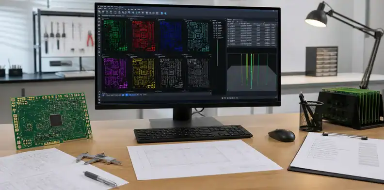
Quick Answer: AI PCB Gerber review should happen before quote upload because export mistakes create holds, wrong pricing, and wrong boards. Check layer set, NC drill, units, outline, polarity, mirroring, paste, BOM/CPL, and revision identity in an independent viewer. CAM can repair some format issues, but it should not guess product intent.
Most failed AI-board quote packages are not dramatic design failures. They are missing drill files, mismatched units, unclear outlines, or old revisions hiding in a ZIP. This article gives the pre-upload review path for buyers who already have generated design files and want to avoid the first CAM hold.
Table of Contents
- What makes a complete Gerber package?
- Why do AI-exported orders get put on hold?
- Is your drill file real NC data?
- Do Gerber and drill units match?
- Where should the board outline live?
- Which polarity and mirror traps matter?
- Which errors can CAM fix?
- What should the quote package include?
- How should revisions be separated?
- What should buyers read back from CAM?
What makes a full Gerber package?
A finished package shows every copper, mask, silkscreen, outline, and drill feature needed to build the quoted board.
For bare boards, include top and bottom copper plus any inner layers, mask artwork, legend layers, routed outline, Excellon drill, tool chart, fabrication drawing, and revision note. For assembly, include paste, BOM, CPL, and assembly drawing.
For a fresh Gerber export, open the ZIP in a viewer that is not the design tool and rebuild the board mentally from the visible layers. The practical reason is that export success does not prove that the manufacturing package is coherent.
For a fresh Gerber export, record the archive name, export date, layer list, drill file, outline source, and viewer used for quote review.
Package rule: If the viewer cannot reconstruct the physical board, the quote package is incomplete.
Why do AI-exported orders get put on hold?
They get held when the export does not match the quote request or leaves CAM to interpret missing data. Move from Gerber troubleshooting to the AI-generated PCB release checklist when the hold reveals a broader release-package gap.
Common holds include absent NC drill, outline drawn on a copper layer, duplicate old files, layer names that do not map to the stackup, and metric/inch mismatch. AI workflows increase this risk because users may export quickly after many generated iterations.
For a quote hold, ask whether the hold is caused by missing data, contradictory data, or a real process limit. The practical reason is that each cause needs a different response and approval owner.
For a quote hold, answer the CAM question in the release note with the affected file name and the design owner who cleared it.
Gerber pre-upload screen:
| Area | Viewer question | Bad result |
|---|---|---|
| Layer set | All expected layers visible? | Wrong stack |
| NC drill | Do holes align? | No holes or shifted holes |
| Outline | One final profile? | Wrong shape |
| Revision | Only current files? | Old build |
Is your drill file real NC data?
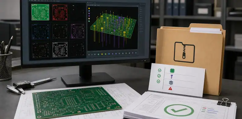
Confirm that holes appear from an NC drill file, not only from a drill drawing or visible pad openings.
A board can show plated pads in copper while the actual Excellon drill file is missing or wrong. Review plated and non-plated holes, slots, tooling holes, and drill units before upload.
For a drill package, check plated holes, non-plated holes, slots, drill units, and tool sizes against the board drawing. The practical reason is that a drill picture is not a substitute for drill data.
If drill data changes, regenerate the Excellon file, drill chart, and plated/non-plated hole notes from one controlled CAD state.
Drill check: If holes vanish in an independent viewer, do not assume CAM can recreate them safely.
Drill data should be checked against the drill drawing and the board image together. Confirm plated and non-plated tools, slots, route paths, finished hole notes, tool units, and any backdrill or press-fit requirements. A viewer screenshot is not a substitute for NC data because the supplier still needs machine-readable coordinates, tool sizes, and plating intent.
Do Gerber and drill units match?
Units and origin should align across copper, drill, outline, and assembly files.
Mixed metric and inch data can shift holes or scale the board. The easiest screen is to measure a known connector pitch, board dimension, or mounting-hole distance in the viewer and compare it with the mechanical requirement.
For a mixed-unit package, measure a known connector pitch or mounting-hole distance in the viewer. The practical reason is that a scale error can look subtle until the fabricated board reaches assembly.
For mixed units, reload copper, drill, and outline files in the same viewer and confirm scale against a known connector or board edge.
Unit mismatch often appears as a board that looks scaled, shifted, or mirrored when layers are loaded together. Check the board outline, drill hits, fiducials, connector edges, and mounting holes against the same origin before sending the archive. If one file uses inch and another uses metric without clear format settings, CAM may stop the quote until the designer re-exports the package.
Where should the board outline live?
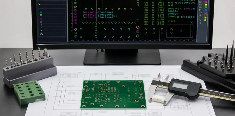
The outline should be on a clear mechanical/profile layer or fabrication drawing, not hidden as an ambiguous copper shape.
CAM needs to know the finished route, V-cut, slots, internal cutouts, tabs, and tolerances. AI-generated boards sometimes export outlines as decorative silkscreen or duplicate profile data on several layers.
For an outline dispute, delete duplicate or decorative outline candidates before sending the final package. The practical reason is that CAM should not choose between several possible finished board shapes.
When outline geometry changes, reissue the mechanical layer or fabrication drawing with slots, routes, tabs, and keepouts under one revision.
CAM fix boundary:
| Issue | Usually safe | Needs approval |
|---|---|---|
| Layer naming | Rename for CAM | Ambiguous stack |
| Panel tooling | Add tabs/fiducials | Change board outline |
| Copper cleanup | Remove artifacts | Move functional copper |
| Drill data | Map clear files | Invent missing holes |
Outline rule: One clear finished-board profile is safer than several competing outlines.
The outline should be unambiguous in the fabrication package, with slots, cutouts, plated edges, castellations, and keepout-sensitive features visible in the same viewer session as copper and drill. If the outline appears only as a mechanical PDF, the supplier may need a controlled drawing note to confirm which geometry drives routing. Treat outline uncertainty as a quote hold, not a cosmetic cleanup.
Which polarity and mirror traps matter?
Check negative planes, mirrored layers, bottom silkscreen, and paste orientation before upload.
Format conversions and automated export presets can invert or mirror layers when the operator does not inspect the final package. This can affect inner plane openings, solder mask, or assembly orientation.
For a mirrored or negative layer, inspect internal planes, bottom-side features, and paste layers for polarity and orientation. The practical reason is that some export mistakes are visually obvious only after a viewer check.
For mirrored or negative layers, save the viewer evidence and require a designer answer before CAM flips or inverts output.
Which errors can CAM fix?
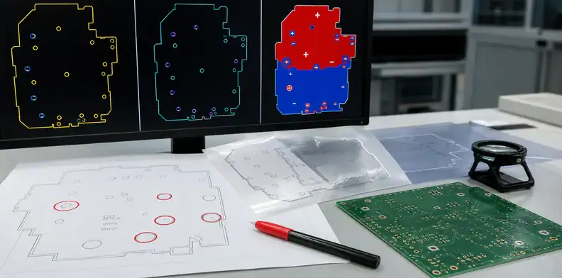
CAM can fix naming, minor cleanup, panel tooling, and some manufacturability edits after buyer approval. The processed Gerber approval page is the better reference once CAM proposes edited manufacturing output.
CAM should not invent missing NC drill, choose a board outline, change copper intent, replace footprints, or decide which old revision is current. Those choices belong to engineering and purchasing before the quote is locked.
For a CAM cleanup request, approve layer naming, fiducials, tabs, or tooling separately from design-changing edits. The practical reason is that the buyer should know when a fix changes the product.
Close a CAM cleanup request by approving only manufacturability edits that do not alter net intent, outline, polarity, or footprint geometry.
CAM boundary: Accept cleanup automatically only when it cannot change function, fit, or acceptance.
CAM can propose manufacturing edits such as teardrops, solder mask relief, panel tabs, small copper cleanups, or drill-chart clarification. It should not decide missing net intent, unidentified board outline, unverified polarity, incorrect footprint pads, or a changed layer order. Those items need design-owner approval because the correction changes what the board is meant to be.
What should the quote package include?
Send the final ZIP, fabrication notes, revision, order quantity, material/finish request, and any known open questions. Bring in AI PCB footprint verification when the quote package depends on land pattern or package identity.
When assembly is included, add BOM, CPL, polarity notes, no-fit parts, consigned items, and programming/test expectations. Use the QueenEMS contact page for a package review when the export was AI-assisted or recently revised.
For a final quote package, attach one current revision and explain any intentional no-fit, panel, or assembly exception. The practical reason is that a clean package reduces the first email cycle before pricing.
A final quote package is controlled when CAM questions are answered, revised files are attached, and open assumptions are visible to purchasing.
How should revisions be separated?
Separate revisions by folder, file name, drawing note, and quote request so old exports cannot mix with current data.
AI-assisted design often creates many iterations quickly. A buyer may drag an old drill file into a new ZIP or keep two board outlines beside each other. Use one final package folder, remove obsolete exports, and include the revision in the fabrication note and email subject.
Revision rule: CAM should receive one current manufacturing package, not a history folder.
Keep each quote archive tied to one revision name, one export date, and one source CAD state. Mixing old drill files with new copper layers is a common way to create false CAM questions. A simple release note that names replaced files, removed options, and open assumptions gives the supplier a cleaner basis for quote comparison.
What should buyers read back from CAM?
Read back any CAM comment that changes a feature, layer, drill, outline, stackup, panel, or assembly input.
Some CAM questions are harmless file-cleanup issues; others change the manufactured board. Ask the supplier to name the affected file and the proposed action. If the answer changes product intent, update the released files or record a controlled approval before the order moves forward.
Readback rule: A CAM approval should identify what changed and what stayed unchanged.
A good Gerber review produces a short release snapshot, not a long forensic report. Record the final ZIP name, revision, viewer used, layer count, outline layer, drill file name, board dimensions, and assembly-file status. That snapshot gives purchasing and CAM a common reference when the supplier asks whether a missing paste file, ambiguous slot, or old NC drill belongs to the current quote.
Readback matters when the supplier fixes anything. If CAM renames layers or adds tooling, the buyer may only need a note. If CAM changes copper, drill data, board profile, impedance stackup, or panel strategy, engineering should approve the revised package. Treat that distinction as part of the order record so the next build does not rely on an undocumented CAM decision.
For Gerber package review, send QueenEMS the exported archive, drill data, outline source, fabrication notes, assembly files when needed, and unresolved CAM questions through the QueenEMS contact page. Call out the revision, panel preference, quantity, and edits that need design-owner approval.
The buyer should read back the CAM assumptions that affect build identity: layer order, drill plating, solder mask openings, board outline, array direction, surface finish, controlled impedance, and any supplier-proposed edits. A short approval note is enough when it points to the exact CAM question and the accepted answer. That prevents the same issue from returning after PO release.
FAQ
Should I review Gerbers if the CAD export said success?
Yes. Export success means files were created, not that the manufacturing package is coherent or aligned.
Can QueenEMS quote from ODB++ instead of Gerber?
Yes, when the package contains the necessary fabrication and assembly data for the quoted scope.
What is the most common Gerber quote hold?
Missing or ambiguous drill, outline, layer map, units, or revision data are common causes of quote delay.
Can I rely on CAM to fix missing Gerber files?
No, CAM can flag missing or conflicting fabrication data, but it should not invent design intent. Missing copper, mask, drill, outline, or polarity data should go back to the design owner before the quote is treated as controlled.
Sources
Written by the QueenEMS Engineering Team
Upload your files today · Free DFM check before production · Ship worldwide
Get your PCB prototypes in as fast as 24 hours. We handle FR4, Rogers, and hybrid boards up to 40 layers in volume production, with advanced builds subject to engineering review — free prototypes for 2–4 layer FR-4 boards, no minimum order.
Just upload your Gerber + BOM — we source every part, assemble, and inspect (AOI + X‑Ray) so you don't have to chase suppliers. Boards ship in as fast as 24 hours.