
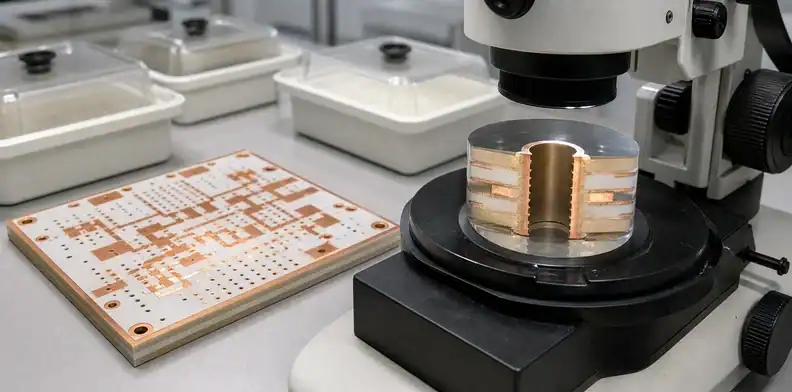
Quick Answer: PTFE PCB hole preparation must produce a clean, activated dielectric surface that copper can wet and bond to without damaging adjacent resin systems. Freeze the exact laminate and bond-ply stack, drilling sequence, PTFE activation process family, time from treatment to metallization, and microsection evidence before release. A generic FR-4 desmear note is not enough because PTFE does not respond to conventional permanganate treatment in the same way as epoxy resin.
Reliable plated through-holes in a PTFE construction begin before copper enters the plating line. Drill heat, tool condition, material order, debris removal, resin-specific desmear and PTFE surface activation determine whether the initial conductive deposit forms a durable interface.
The problem becomes more difficult in a hybrid board. A single hole may pass through ceramic-filled PTFE, woven-glass epoxy, bond ply and copper interfaces, each with different preparation needs. This article keeps the decision on that material-specific hole wall, rather than repeating the broader hybrid PCB via reliability review.
Table of Contents
- Identify every material the drill crosses
- Set drilling controls around PTFE behavior
- Separate desmear from PTFE activation
- Choose a qualified treatment process
- Protect the activated surface before metallization
- Inspect copper coverage and interface quality
- Control hybrid stacks as one process sequence
- Manage substitutions and repeat-order changes
- Issue a quote-ready hole preparation package
Identify every material the drill crosses
Material rule: The approved preparation route must match every laminate, bond ply, filler, and copper interface exposed by the finished drill path.
Hole preparation cannot be selected from the surface laminate name alone. The drill path may include PTFE composite cores, thermoset ceramic-filled laminates, FR-4 cores, low-flow bond plies, copper foils and plated or filled substructures. Each interface changes heat generation, smear behavior, cleaning response and adhesion risk.
Build a hole-family map before quotation. Group holes by diameter, start and stop layers, aspect ratio, drill direction, finished function and material sequence. A through-hole crossing the full hybrid stack is not equivalent to a mechanically drilled hole contained in the FR-4 section or a laser microvia stopping on a PTFE-adjacent target.
The stack-up should identify manufacturer, grade, nominal thickness, copper type and bond material. “Rogers + FR-4” is not a controlled material callout. Rogers product families include PTFE and thermoset systems with different fabrication guidance, while the FR-4 and bond-ply selections can change desmear and thermal behavior.
When the material architecture is still being selected, use the high-frequency hybrid stack-up RFQ requirements to freeze electrical and construction decisions first. The hole preparation plan can then be qualified against one defined stack instead of a placeholder material family.
Include non-electrical holes if their wall condition or later plating matters. Plated slots, ground stitching holes, press-fit holes and mounting holes near RF launch structures can impose different finished diameter, copper or mechanical requirements even when they share a drill program.
Set drilling controls around PTFE behavior
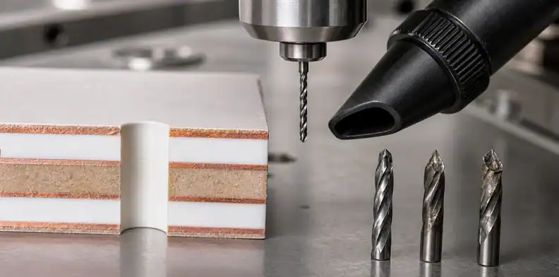
PTFE-based materials can be soft, abrasive or heavily filled depending on formulation. Drill heat can smear polymer across the hole wall, while ceramic filler accelerates tool wear and can leave an irregular surface. A parameter set that works for one grade or one bond film should not be assumed equivalent for another.
The supplier owns spindle speed, infeed, chip load, entry and backup materials, stack height and hit count. The buyer should require a qualified result and ask how tool life is established. Rogers fabrication guidance for RT/duroid 6002, for example, ties replacement to hole quality rather than waiting for tool breakage and identifies smear, nail-heading and deflection as relevant observations.
Useful release questions include:
- Is the drill new or resharpened where the material guidance restricts tool condition?
- Which side enters the drill when only one outer layer is PTFE?
- How is debris removed without deforming a soft hole edge?
- Does one drill stack combine materials that need conflicting parameters?
- How are hit count and tool wear linked to inspection?
- What evidence triggers tool replacement or program adjustment?
Do not copy example drilling parameters from a datasheet into every purchase drawing. They are starting points tied to a product, equipment and construction. Request confirmation that the supplier’s qualified process follows the current laminate guidance and produces the agreed hole quality.
Separate desmear from PTFE activation
Treatment rule: Removing thermoset smear and activating PTFE are different process objectives, so evidence for one cannot be used as proof of the other.
Desmear and activation solve different surface problems. Conventional epoxy desmear removes resin smear and exposes a suitable interface after drilling. PTFE activation changes a chemically inert, low-energy surface so that metallization can adhere. Calling both operations “desmear” hides the critical distinction.
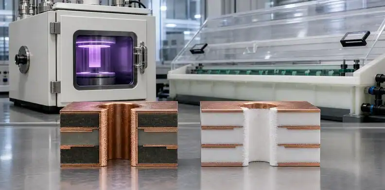
In a hybrid hole, the sequence must address each resin without degrading another. Permanganate chemistry that is effective on epoxy is not a universal PTFE treatment. A plasma cycle used to remove thermoset smear may differ from a cycle intended to activate PTFE. Sodium-based treatment can create a highly bondable PTFE surface, but handling, exposure and downstream cleaning must be controlled.
Ask the supplier to describe the process family, order and qualified material scope. The answer should make clear:
- how drill debris is removed;
- how thermoset smear is treated, if present;
- how the PTFE surface is activated;
- how residues from treatment are removed;
- how the panel is protected and transferred to metallization.
The broader hybrid desmear and plating control owns cross-material risk across many hybrid constructions. This article narrows the acceptance to the PTFE interface and the evidence that proves copper adhesion there.
Choose a qualified treatment process
Plasma and sodium-based treatments can both appear in PTFE processing guidance, but they are not interchangeable labels. Equipment type, gas chemistry, pressure, power, temperature, cycle time, panel loading and material composition influence the result. Treatment that is too weak can leave an unbondable surface; an unsuitable or excessive process can affect nearby materials and feature geometry.
The purchasing specification should avoid freezing proprietary recipes unless the customer owns a validated process. Instead, require the supplier to identify the approved process family and to confirm compatibility with every material in the hole path.
Compare treatment choices through outputs:
| Control point | Evidence to request | Release concern |
|---|---|---|
| Material compatibility | Current laminate and bond-ply processing guidance | A legacy process may not cover the ordered revision |
| Surface activation | Qualified process record or representative adhesion evidence | Copper may deposit but separate under thermal stress |
| Hole cleanliness | Microsection or controlled visual evidence | Residue can be hidden beneath initial metallization |
| Adjacent resin condition | Section through material interfaces | Aggressive treatment can cause recession or roughness |
| Transfer to plating | Defined handling and maximum controlled delay | Activated PTFE can be contaminated before copper deposition |
Rogers AD Series guidance notes that plasma-treated holes are more delicate than sodium-etched holes and warns against pressure washing or scrubbing before metallization. That is exactly why the approval should include handling after treatment, not only the treatment name.
Protect the activated surface before metallization
Handling rule: Control the transfer from activation to metallization because delay, contamination, or uncontrolled contact can invalidate an otherwise capable treatment.
An activated hole wall can be lost through contamination, moisture, mechanical handling or an uncontrolled delay. The process route from treatment to conductive deposition should therefore be treated as one linked operation.
Ask whether panels are baked, how they are stored between steps, whether they encounter brushing or pressure wash, and what maximum hold time is qualified. The appropriate answer depends on the material and activation method. The buyer does not need an operator instruction sheet, but does need assurance that the quoted route preserves the prepared surface.
Initial metallization may use electroless copper or a qualified direct-metallization process. The deposit must cover the PTFE and other dielectric surfaces continuously enough to support subsequent electrolytic plating. A conductive appearance is not the same as a bonded interface, so visual coverage should be paired with microsection and reliability evidence appropriate to the order.
Keep moisture control connected to the material package. A bake inserted without material justification can affect dimensional condition or mask later process problems, while inadequate drying can trap moisture before copper buildup. The supplier should follow current material guidance and state any preconditioning that affects quotation or lead time.
Inspect copper coverage and interface quality
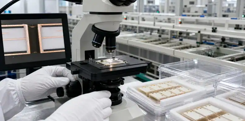
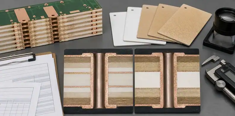
Microsection evidence should show the PTFE interface, adjacent resin systems, inner-layer copper connections and plated barrel. Choose an orientation that passes through the most difficult material transition and enough representative holes to show process consistency.
Review the section for:
- smear or debris remaining on the dielectric or copper interface;
- excessive resin recession, glass or filler protrusion;
- continuous initial and electrolytic copper coverage;
- voids, folds, nodules or cracks in the plated wall;
- separation at PTFE, bond-ply or copper interfaces;
- inner-layer connection condition and any nail-heading;
- finished hole diameter and copper distribution where controlled.
The report needs lot, panel, hole family, layer identification, location, magnification and measured values. A polished photograph without construction identity cannot prove that the section represents the RF holes or material interfaces in question. Use the established microsection report fields and add the exact PTFE grade and treatment route.
Electrical test confirms the connection after fabrication. Thermal testing or interconnect stress evidence may be needed for high-reliability, high-aspect-ratio, multiple-lamination or severe assembly conditions. Match the specimen to the ordered stack; a generic FR-4 coupon does not qualify a PTFE interface.
Control hybrid stacks as one process sequence
Hybrid check: Accept the route only when drilling, thermoset cleaning, PTFE activation, and copper initiation remain compatible across the complete mixed-material wall.
Hybrid construction creates interactions that a material-by-material checklist can miss. Drill conditions chosen for ceramic-filled PTFE can affect an epoxy bond film. Plasma selected for thermoset smear can leave PTFE insufficiently activated. Lamination conditions can alter hole-entry flatness and registration before drilling begins.
Review the route in order:
- material conditioning and lay-up;
- lamination and dimensional stabilization;
- drill direction, stack and tool-life control;
- debris removal and resin-specific desmear;
- PTFE activation;
- protected transfer to metallization;
- initial deposition and electrolytic copper buildup;
- microsection, electrical and reliability evidence.
A change at one stage should trigger review of later assumptions. Substituting a bond ply may change drilling smear and plasma needs. Reversing stack orientation may change drill entry. Adding a copper plane can alter heat and plating distribution. The existing hybrid lamination evidence requirements help control the upstream construction so hole preparation is not qualified against a moving target.
Panelization matters as well. Hole density and current distribution can affect copper buildup, while panel edges and tooling areas may experience different process conditions. Define representative section locations rather than accepting the easiest coupon position.
Include blind or buried structures in the route review even when they use a separate drill step. A subpart may be drilled and plated before final lamination, then exposed to additional heat and chemistry later. The evidence plan should state which interface is inspected at the subpart stage and which is verified after the completed stack is processed. This prevents an early acceptable section from being treated as proof of a later altered interface.
| Hybrid-wall region | Process question |
|---|---|
| PTFE laminate | How is the low-energy surface activated for copper adhesion? |
| Thermoset bond ply | How is smear removed without excessive recession? |
| Ceramic-filled or woven region | How are protruding filler or glass conditions evaluated? |
| Material boundary | Which section proves continuous copper across the interface? |
Manage substitutions and repeat-order changes
Material substitution is the highest-risk shortcut in this process. Similar dielectric constant or thickness does not prove equivalent drilling, activation or adhesion behavior. A new PTFE grade, filler system, copper treatment or bond film requires a documented assessment before the existing hole preparation route is reused.
Require the change request to state the original and proposed material, affected layers, technical reason, processing differences, evidence plan and production applicability. If the substitute is used for a prototype only, mark it as an engineering exception rather than silently changing the repeat-order baseline.
Process changes also include a new plasma tool, chemistry family, drill vendor, panel size, stack height, metallization route or outsourced operation. The supplier should evaluate whether the qualified evidence still represents the new route. Buyers do not need to approve routine maintenance, but they do need notification and requalification when the controlled process identity changes materially.
For repeat orders, retain the approved stack-up, material certificates, process-family declaration and representative section format. Compare current evidence with the baseline instead of relying on the purchase-order part number alone.
Issue a quote-ready hole preparation package
Quotation rule: Every supplier should quote the same material stack, drill families, treatment evidence, and substitution limits so a lower price does not hide omitted preparation steps.
A useful RFQ lets each supplier quote the same material architecture and proof burden. Send the stack-up with exact laminate and bond-ply grades, copper weights, finished thicknesses, hole table, drill files, aspect ratios, controlled impedance, surface finish, acceptance class and assembly thermal profile when relevant.
| Controlled item | Evidence expected before release |
|---|---|
| Drill path | Material sequence, hole family, tool-life method and drill direction |
| Wall preparation | Thermoset-cleaning and PTFE-activation process families |
| Metallization transfer | Handling controls and qualified time between preparation and copper |
| Lot acceptance | Representative sections, electrical test and material/process identity |
Add a PTFE hole preparation note that requests:
- a material-by-layer drill-path review;
- confirmation of drill direction and qualified tool-life control;
- the thermoset desmear and PTFE activation process families;
- controlled handling between activation and metallization;
- representative microsection locations and report fields;
- electrical and thermal evidence appropriate to the construction;
- approval before material or process-family substitution;
- the repeat-order baseline and change-notification owner.
Compare quotations for hidden assumptions. A low price may exclude special plasma, sodium treatment, representative sections or material-specific testing. A longer quote may include the exact controls needed to prevent a plated barrel from separating after assembly.
Use the QueenEMS contact page to submit the stack-up, laminate datasheets, bond materials, hole table, drill path, plating requirement, evidence plan, order quantity, and supplier exceptions. A fabrication review can then separate material-processing limits from design margin or missing documentation before a production purchase order.
FAQ
Can ordinary FR-4 desmear prepare a PTFE hole wall?
No. Conventional epoxy desmear does not provide the same PTFE surface activation. A hybrid route must address thermoset smear and PTFE adhesion as separate but coordinated steps.
Is plasma always better than sodium treatment?
No. Both can be qualified for particular materials and equipment. Compare material compatibility, activation result, handling sensitivity, metallization timing and verified interface quality.
What should a PTFE hole microsection identify?
It should identify the material stack, treatment route, hole family, panel location and lot while showing cleanliness, copper continuity, dielectric condition, interfaces and finished geometry.
Can an electrical test replace PTFE adhesion evidence?
No. Continuity can pass even when the copper-to-dielectric interface is weak. Use material-specific process qualification and representative physical evidence in addition to net testing.
Sources
- Rogers Corporation, Fabrication Guidelines for AD Series Laminates
- IPC, High Frequency Circuit Materials Used in the PCB Industry
Written by the QueenEMS Engineering Team
Upload your files today · Free DFM check before production · Ship worldwide
Get your PCB prototypes in as fast as 24 hours. We handle FR4, Rogers, and hybrid boards up to 40 layers in volume production, with advanced builds subject to engineering review — free prototypes for 2–4 layer FR-4 boards, no minimum order.
Just upload your Gerber + BOM — we source every part, assemble, and inspect (AOI + X‑Ray) so you don't have to chase suppliers. Boards ship in as fast as 24 hours.