
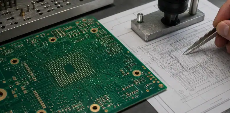
Quick Answer: An HDI registration budget is the layer-to-layer alignment margin left after sequential lamination, drilling, imaging, and copper features are considered. Protect microvia landing pads by agreeing the actual build-up, target pad geometry, annular margin, and fabricator registration capability before routing density forces an unmanufacturable structure. Do not use a generic minimum annular-ring number as proof that a multi-lamination HDI stack-up is safe.
- Registration is a construction capability, not only a CAD coordinate check.
- Each sequential build-up adds alignment and process dependencies.
- Capture-pad margin must be reviewed with laser-via size, target pad, copper growth, and approved stack-up.
- The RFQ should request a proposed build and an explicit CAM response for critical microvia structures.
HDI registration budget is the space between a theoretical microvia landing pattern and the combined movement the fabrication process must absorb. A layout can look perfect at nominal coordinates and still leave too little margin after sequential lamination, image alignment, laser drilling, copper build, and target-pad tolerance are considered. The result can be breakout risk, poor interconnection, or a late CAM hold when the supplier sees the actual density.
The HDI construction guide covers the wider choice among build-up types. This article deals with one practical release question: how to translate dense microvia routing into a registration budget that a fabricator can review before the board is committed.
Table of Contents
- What a registration budget includes
- Why sequential lamination changes the margin
- How capture pads and annular margin work together
- Which layout features need a separate CAM check
- How to use supplier capability without copying generic limits
- What evidence should accompany the first build
- How to release a repeatable HDI construction
What a registration budget includes
An HDI registration budget combines the alignment tolerances that affect whether a laser-drilled microvia lands on its intended target pad with enough copper margin to form a reliable connection. It is not one number copied from a capability chart. It depends on the build-up sequence, dielectric thickness, target-pad geometry, laser-via diameter, artwork registration, copper process, and the fabricator’s proven capability for that construction.
The design team owns the functional intent: which BGA pins require via-in-pad, which layers must connect, and what routing density cannot change. The fabricator owns the process assessment: whether the proposed capture pad, via geometry, and buildup can be registered with a reasonable production margin. The handoff fails when either side assumes the other has already calculated the whole budget.
A useful review identifies the critical structures instead of treating all microvias as equal. A single dense escape region under a fine-pitch BGA can drive the entire construction. Mark those regions in the data package and ask for a CAM response tied to the actual stack-up revision.
Release rule: The microvia target pad must be approved in the context of the sequential build, not only against a generic drawing minimum.
Why sequential lamination changes the margin
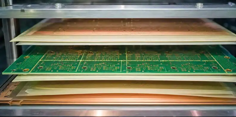
Sequential lamination creates one or more buildup stages around a core. Each stage adds material, imaging, drilling, plating, and alignment dependencies. A simple 1+N+1 structure may have a different registration challenge from a deeper buildup, an any-layer approach, or a construction that combines buried vias with stacked microvias.
The point is not that more buildup stages are inherently unacceptable. They are often necessary for routing density. The point is that a registration allowance appropriate for one structure cannot automatically be reused for another. When the layer count, lamination sequence, or target-pad chain changes, the supplier should reassess the critical landing geometry.
| Construction question | Why it changes registration review | Buyer action |
|---|---|---|
| How many buildup stages? | Changes the alignment path | Provide the intended stack-up type |
| Is the microvia stacked or staggered? | Changes fill, plating, and target relationship | Mark via structure in drill notes |
| Does the via land under a BGA pad? | Limits available escape and inspection margin | Flag the component and pad class |
| Are buried vias part of the core? | Adds drilling and lamination dependencies | State spans and sequence |
Before specifying a construction, compare it with the HDI stack-up types. The objective is to select a build that supports the routing problem without forcing capture pads below what the fabricator can control.
Build check: Recalculate the landing margin whenever the number of buildup stages or via stack changes.
How capture pads and annular margin work together
A capture pad provides the copper area that receives the microvia. The remaining copper around the drilled or plated feature is the practical margin that helps the interconnection survive process variation. Both must be considered with the finished feature, not just the nominal CAD hole. A small via does not automatically allow a proportionally small target pad when registration, copper growth, and layer movement are part of the process.
This is where generic annular-ring rules can mislead. A through-hole annular requirement may not describe a laser microvia’s landing geometry. A manufacturer capability chart may show a theoretical minimum that is suitable only for a named material set and process class. The correct question is whether the complete target structure has enough documented margin for the proposed buildup.
Use the PCB annular-ring breakout acceptance article for the broader distinction between nominal artwork and inspection acceptance. For HDI, add the sequential-lamination construction and laser-via target pad to the review.
Which layout features need a separate CAM check
Ask for a specific CAM check where microvias are tightly packed, stacked, buried under component pads, near anti-pad boundaries, or adjacent to unusual copper distribution. These features can combine routing pressure with limited process margin. A broad note saying “fabricate to capability” is not enough when the layout depends on a narrow landing geometry.
The data package should include the ODB++ or Gerber set, drill information, stack-up, fabrication drawing, and a marked image or coordinate list of critical BGA and microvia regions. The mark-up need not duplicate every coordinate; it should make clear which structures cannot be changed without design approval.
For laser process evidence, use the PCB laser drilling and microvia acceptance article. It helps define what the fabricator should review after the target geometry has been identified.
Fabrication check: Mark a dense BGA escape as a controlled region when its target pad cannot be changed without routing consequences.

How to use supplier capability without copying generic limits
Supplier capability should be used as a conversation starter, not copied blindly into design rules. Ask what the published number represents: which material, buildup count, panel size, copper condition, target pad, and acceptance method. A capable supplier may offer a narrow feature under controlled conditions yet advise a larger land for a volume build with different registration risk.
Compare quotes on the same construction. If one supplier proposes a different layer count, glass style, target-pad size, or via fill method, the pricing comparison is no longer a simple manufacturing-cost comparison. It is a technical change that may alter routing, signal integrity, and reliability.
The HDI microvia aspect-ratio article addresses another part of feasibility. Use it with this registration review; aspect ratio and target-pad margin solve different failure modes.
Request capability in the form of a proposal rather than a yes/no claim. The supplier should identify the proposed target-pad diameter, finished laser-via geometry, buildup dielectric, and the condition under which its registration capability applies. That response gives engineering something concrete to approve or challenge. A chart with a single smallest feature does not establish that all those features can coexist in one dense panel.
When two suppliers offer different land sizes, do not force the smaller one to match the larger merely to make the quote look competitive. Compare the resulting routing, testability, expected yield, and qualification burden. The economical choice is often the construction that leaves a visible process margin rather than the one that reaches the smallest possible nominal geometry.
What evidence should accompany the first build
For a first build, request evidence that corresponds to the risk. This may include the approved stack-up, CAM questions and answers, a microsection plan for representative structures, and a statement of whether the supplier changed any microvia or target-pad assumption. If a build uses stacked microvias, define the fill and plating evidence needed to review the connection path.
The sample should also have a decision path. A passing result can release the structure for the named revision. A marginal result can prompt a larger capture pad, a different buildup, or a routing change. Do not quietly modify several variables at once, because the next build will not show what actually solved the risk.
For reliability-oriented structures, link the evidence to the HDI microvia thermal-cycling qualification article. A thermal-cycle result is meaningful only when the tested board construction matches the one being approved.
How to release a repeatable HDI construction
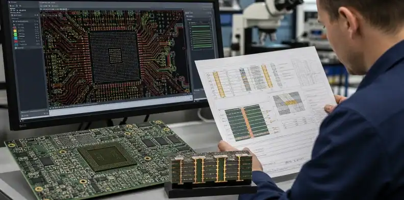
Start the release record with a drawing-level description of what is non-negotiable. That can include specific microvia spans, an approved capture-pad range, a named buildup sequence, or the BGA areas that cannot accept a routing change. Then let the fabricator state the process values it will use to meet those requirements. This division preserves the design intent while allowing a real manufacturability response.
Release the HDI construction as a controlled package. Record the layer sequence, material set, buildup stages, via spans, target-pad assumptions, and any approved supplier-specific geometry. Keep the CAM response with the same revision as the drawing and fabrication files. This allows purchasing to identify a quote change that would otherwise look like a harmless material or capability substitution.
On repeat orders, compare the supplier’s proposed construction with the approved record before releasing the purchase order. Any change to the buildup sequence, target pads, laser-via geometry, or material construction should return to engineering for review. This is especially important when a new supplier quotes a lower price by proposing a different HDI route.
The release file should identify the escalation trigger. For example, it can require a CAM question if the fabricator must change a target-pad size, layer span, dielectric construction, or via stack. This prevents a production team from treating a registration-driven change as a routine panel optimization. It also gives purchasing a clear reason to hold a quote that cannot reproduce the approved geometry.
For a second source, request the same build description and compare it line by line with the approved one. The point is not to force identical equipment or wording; it is to determine whether the new supplier has changed the construction that the original evidence supports.
For a second source or repeat order, compare the BGA escape, via span, capture pad, and buildup table against the approved revision. Require a CAM question when any marked microvia region changes; that is the point at which a lower quote becomes a construction change.
| Issue | Traceable build field | CAM escalation |
|---|---|---|
| Smaller capture pad | Approved target-pad range | Ask before changing a marked BGA escape |
| Different buildup | Layer sequence and material set | Recheck registration budget |
| Revised via span | Named start and stop layers | Review landing pads and test scope |
Repeat rule: A supplier change is acceptable only after its proposed HDI construction is compared with the evidence for the approved revision.
QueenEMS can review a dense HDI release package when you provide the stack-up, BGA pitch and escape approach, microvia spans, target-pad geometry, critical regions, and intended order quantity. The output can identify items that need CAM confirmation before an HDI quote becomes a production approval. Use the QueenEMS contact page to send the package.
FAQ
Can a standard annular-ring rule approve an HDI microvia pad?
No. A microvia landing pad must be reviewed with the laser feature, target pad, buildup sequence, and supplier registration capability. A generic through-hole rule does not describe that full condition.
Does more sequential lamination always require a larger pad?
Not automatically. It increases the need for a construction-specific review. The supplier should evaluate the actual buildup and propose a capture-pad margin that fits its qualified process.
What should I mark in the fabrication data?
Mark the critical microvia regions. Identify fine-pitch BGA escapes, stacked structures, and any target pad that cannot change without engineering approval.
Is a microsection enough to approve the first HDI lot?
Only when it answers the stated risk. Use it with the approved stack-up, CAM response, and any required reliability evidence rather than as an isolated photograph.
Sources
- IPC, Effects of Dielectric Material, Aspect Ratio and Copper Plating on Microvia Reliability
- IPC, A DOE to Assess PCB Fabrication Material Design and Process Using IST
Written by the QueenEMS Engineering Team
Upload your files today · Free DFM check before production · Ship worldwide
Get your PCB prototypes in as fast as 24 hours. We handle FR4, Rogers, and hybrid boards up to 40 layers in volume production, with advanced builds subject to engineering review — free prototypes for 2–4 layer FR-4 boards, no minimum order.
Just upload your Gerber + BOM — we source every part, assemble, and inspect (AOI + X‑Ray) so you don't have to chase suppliers. Boards ship in as fast as 24 hours.