
Quick Answer: HDI PCB material selection dictates 30% to 50% of your total board cost and determines your signal reach. Base Standard High-Tg FR-4 handles sub-1Gbps signals at a 1x cost multiplier. Moving to Mid-Loss (1-10 Gbps) costs 1.5-2x, Low-Loss (10-25 Gbps) costs 3-4x, Ultra-Low-Loss (25-56 Gbps) costs 5-8x, and RF-Grade (mmWave) runs 6-10x standard pricing.
Key takeaways:
- Standard FR-4: Df ~0.020, handles <1 Gbps, 7-10 day lead time.
- Low-Loss limits: Required for 10 Gbps traces longer than 6 inches (Df ~0.005).
- Ultra-Low-Loss yield: First-pass yield drops to 96.8% versus 99.5% for standard materials.
- Mixed build-ups: Mixing Rogers (CTE ~50 ppm) with FR-4 (CTE ~250 ppm) drops yield by 5-10%.
Table of Contents
1. What Is HDI PCB Material Selection and Why Does It Matter for Signal Integrity?
2. How Do You Match HDI Material to Your Application?
3. When Does Standard High-Tg FR-4 Work for HDI Designs?
4. When Should You Step Up to Mid-Loss Laminates?
5. Which Low-Loss Materials Suit 10-25 Gbps HDI Designs?
6. What Ultra-Low-Loss Options Exist for 25+ Gbps Applications?
7. When Do You Actually Need RF / Microwave-Grade Materials?
8. How Does HDI PCB Material Selection Affect Cost and Lead Time?
9. How Do You Specify HDI Material in Your Fabrication RFQ?
Picking the wrong material for an HDI board causes immediate impedance drops and high insertion loss. Many hardware engineers try to guess the right laminate, often overpaying by 300% for an ultra-low-loss substrate when a mid-loss option would pass all signal integrity tests. On our manufacturing floor at QueenEMS, we process over 50,000 HDI boards annually, and we see this exact material upgrade myth every single day. The solution requires a strict framework based on application and signal speed, rather than jumping straight to the most expensive brand name. This guide breaks down HDI PCB material selection into five distinct engineering categories to give you a reliable, cost-effective decision matrix.
1. What Is HDI PCB Material Selection and Why Does It Matter for Signal Integrity?
HDI material selection is the process of matching a substrate’s Dielectric Constant (Dk between 3.0 and 4.4) and Dissipation Factor (Df between 0.002 and 0.020) to your specific signal speed requirements. The physical properties of the laminate directly control how far a high-speed signal can travel before degrading and how well the microvias survive thermal cycling during assembly.
To make an accurate selection, you must evaluate these specific metrics:
- Dk (Dielectric Constant): Dk is the measure of how a material stores electrical energy, directly affecting trace impedance. Lower Dk values (around 3.0-3.4) make it easier to design exact 50Ω traces with manageable widths on thin HDI dielectric layers.
- Df (Dissipation Factor / Loss Tangent): Df represents the energy lost as heat, controlling insertion loss. A lower Df (like 0.002) allows signals to travel further distances without requiring heavy active equalization.
- Tg (Glass Transition Temperature): Tg is the temperature point where resin softens, strictly requiring 170-180°C grades for HDI boards to survive multiple sequential lamination cycles.
- CTE z-axis (Coefficient of Thermal Expansion): This measures how much the board expands vertically when heated. Lower CTE values prevent microvia barrel cracking during the 260°C reflow process.
Here is the reality: You cannot ignore industry standard testing. The IPC-4101E specification defines base material classifications, providing the core Dk, Df, and CTE test methods that you will see on every valid laminate datasheet.
Bottom line: Never select an HDI laminate based on brand reputation; always match the material’s specific Dk and Df values to your maximum insertion loss budget.
2. How Do You Match HDI Material to Your Application?
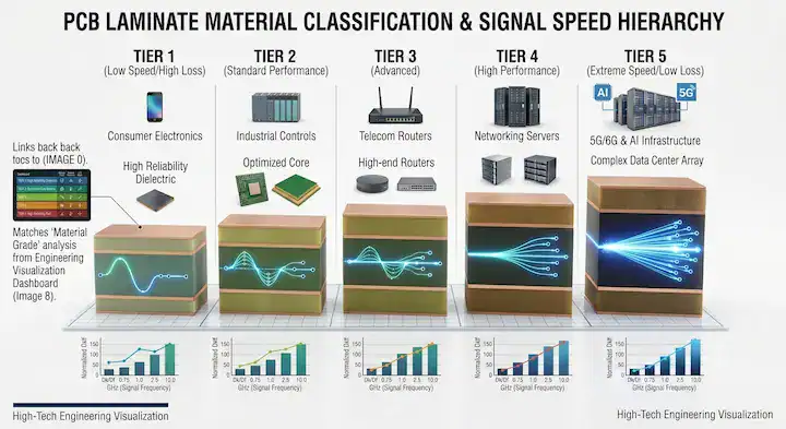
You match HDI material to your application by calculating your maximum trace length and signal frequency, then plotting those numbers onto a 5-category framework that scales from 1x base cost up to a 10x cost multiplier. Categorizing materials by performance tiers separates your engineering needs from whatever specific brand a fab happens to stock.
Table 1: The 5-Category HDI Material Framework
| Category | Df @ 10GHz | Dk @ 10GHz | Tg (°C) | Z-Axis CTE (ppm) | Cost Multiplier | Example Models |
|---|---|---|---|---|---|---|
| 1. Standard High-Tg | ~0.020 | ~4.4 | 170-180 | 220-250 | 1x (Base) | Isola 370HR, Shengyi S1000-2M |
| 2. Mid-Loss | ~0.008-0.015 | ~3.8-4.0 | 175+ | 180-220 | 1.5-2x | Isola IS415, Shengyi S7136 |
| 3. Low-Loss | ~0.004-0.008 | ~3.4-3.8 | 200+ | 150-180 | 3-4x | Megtron 4, Isola I-Tera MT |
| 4. Ultra-Low-Loss | ~0.002-0.004 | ~3.0-3.4 | 200+ | < 150 | 5-8x | Megtron 7, Astra MT77 |
| 5. RF/Microwave | < 0.002 | ~3.0-3.5 | N/A (Ceramic) | 50-70 | 6-10x | Rogers 4350B, Taconic RF-35 |
Choose Standard High-Tg if your system runs sub-1Gbps signals. Step up to Low-Loss only if your application hits the 10-25 Gbps threshold on traces longer than six inches.
Think about this scenario: A networking equipment customer in Massachusetts came to us specifying Megtron 7 for their 25G switch design. Their reasoning: “We want to future-proof for 56G.” We reviewed the signal trace lengths and equalization budget—longest trace was 8 inches with a 4 dB insertion loss budget. At 25 Gbps on Megtron 4 (Df 0.005), they would consume ~3.2 dB, staying safely within budget. Megtron 7 would consume ~1.4 dB, which was absolute overkill. We proposed Megtron 4 and ran a simulation: signal margins were healthy, and there was no eye closure. The cost saving was $42 per unit on a 2,000-unit production run, totaling $84,000 saved. Six months later, they confirmed zero field issues. The lesson we share with clients is simple: “future-proofing” by jumping two material categories costs a massive amount of money but rarely buys you a functional future-proof design. By the time you actually upgrade the processors to 56G, you will redesign the whole stackup anyway.
Users on Stack Exchange often ask: “Can I mix Rogers 4350 and FR-4 in the same HDI stackup? My layout wants to use Rogers only on RF layers but FR-4 for the rest. Is this even doable?” Yes, mixed material build-up is viable, but it carries strict mechanical limitations.
- CTE Mismatch: Rogers 4350 features a z-axis CTE around 50 ppm, while FR-4 sits near 250 ppm. This massive difference generates heavy stress on microvias during thermal cycling.
- Yield Impact: You will lose 5-10% of your first-pass yield compared to a homogeneous stackup.
- Process changes: The factory must utilize a hybrid lamination press profile to bond the incompatible resin systems.
Table 3: Recommended Material Categories by Application
| Application Sector | Typical Data Rate | Recommended Category | Justification |
|---|---|---|---|
| IoT / Wearables | < 1 Gbps | 1. Standard High-Tg | Low cost, handles tight HDI pitches perfectly. |
| Automotive ADAS | 1-5 Gbps | 2. Mid-Loss | Balances thermal reliability with moderate signal needs. |
| 5G Small Cell | 5-10 Gbps | 2. Mid-Loss | Controls insertion loss for medium-length traces. |
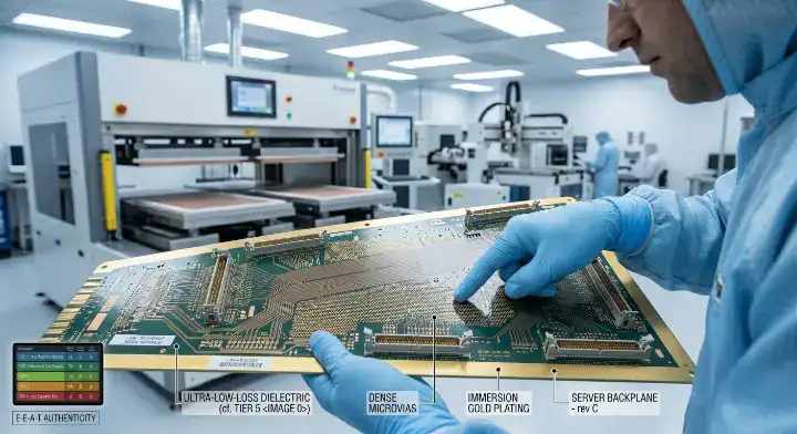
| Server Backplane | 10-25 Gbps | 3. Low-Loss | Maintains signal integrity across long backplane routes. |
| AI / ML Processor | 25-56 Gbps | 4. Ultra-Low-Loss | Required for PAM4 signaling and tight loss budgets. |
| Radar / mmWave | 24 GHz + | 5. RF-Grade | Requires strictly stable Dk across wide frequency bands. |
Use Mid-Loss for 5G small cells and ADAS modules. Reserve Ultra-Low-Loss purely for AI accelerators and high-end server environments handling PAM4 signals.
Bottom line: Always calculate your total insertion loss budget mathematically before you upgrade to a more expensive material category.
3. When Does Standard High-Tg FR-4 Work for HDI Designs?
Standard High-Tg FR-4 works perfectly for HDI designs running sub-1Gbps signals, offering a 1x base cost multiplier and standard 7-10 day lead times. Materials in this tier deliver a Tg of 170-180°C, a Dk around 4.4, and a Df near 0.020 at 1GHz, making them the absolute backbone of consumer electronics.
You should specify this category for:
- Consumer HDI devices like smartphones and tablets.
- IoT wearables requiring extremely dense 3-stage microvias but low operating frequencies.
- Any low-speed design utilizing standard FR-4 material properties and Tg grades.
Standard High-Tg is highly processable. Because the resin flows predictably, factories hit 99.5% yield rates without custom press profiles. Representative examples include Isola 370HR, Shengyi S1000-2M, and Nelco N4000-13EP.
What to watch out for: Do not use this category if you need strict impedance control on extremely long traces, as the Dk variation between different glass weaves will cause impedance swings.
Bottom line: Stick to Standard High-Tg FR-4 for any HDI board operating under 1 Gbps to keep your manufacturing costs at the absolute baseline.
4. When Should You Step Up to Mid-Loss Laminates?
You must step up to Mid-Loss laminates when your signals cross the 1-10 Gbps threshold, accepting a 1.5-2x cost multiplier and a 14-18 day lead time to drop your Df into the 0.008-0.015 range. This category serves as the transitional bridge, dropping the Dk down to 3.8-4.0 to make thinner dielectrics viable.
This tier is highly effective for:
- Networking edge devices processing gigabit traffic.
- 5G small cell hardware requiring better thermal and electrical stability.
- Designs utilizing HDI stackup design 1+N+1 vs 2+N+2 geometries with moderate trace lengths.
If your layout forces traces over 4 inches at 5 Gbps, standard FR-4 will eat up your loss budget rapidly. Mid-Loss materials, such as Isola IS415, Park Nelco N4000-13SI, or Shengyi S7136, cut that insertion loss by nearly half without forcing you into premium pricing tiers.
Bottom line: Upgrade to Mid-Loss only when standard FR-4 fails your pre-layout simulation for signals sitting between 1 and 10 Gbps.
5. Which Low-Loss Materials Suit 10-25 Gbps HDI Designs?
Low-Loss materials featuring Df values between 0.004 and 0.008 suit 10-25 Gbps designs by preserving signal reach, though they require a 3-4x cost multiplier and 14-18 days for material procurement. Laminates in this category drop the Dk to roughly 3.4-3.8, which is heavily required for server backplanes and 5G mid-band switches.
If you are evaluating these materials, you must refer to the IPC-TM-650 Method 2.5.5.5 standard, which establishes the strict stripline testing for Permittivity and Loss Tangent at high frequencies like 10GHz and 20GHz. Representative models include Panasonic Megtron 4, Megtron 6, Isola I-Tera MT, and Shengyi S7439.
Engineers on r/PrintedCircuitBoard frequently hit this wall: “What HDI material do I need for a 10 Gbps signal? My current FR-4 is causing too much insertion loss but I do not know how much to upgrade. Help me decide between Mid-Loss and Low-Loss.” At exactly 10 Gbps, you sit on the direct boundary between categories. The decision relies entirely on physical trace length and your total insertion loss budget (typically maxed at 8-10 dB):
- Trace Length < 6 inches: A Mid-Loss laminate (Df ~0.010) works perfectly, contributing roughly 0.5 dB of insertion loss per inch.
- Trace Length 6-12 inches: You must upgrade to Low-Loss (Df ~0.005). Otherwise, standard insertion loss will surpass 4 dB, and signal reach will fail.
- Trace Length > 12 inches: Even at 10 Gbps, pushing past 12 inches requires Ultra-Low-Loss materials combined with active equalization.
- The formula: Calculate your total IL budget = trace length × loss/inch. If it exceeds 10 dB, upgrade the material tier.
Table 2: Material Category by Signal Speed Threshold
| Signal Speed | Trace Length | Recommended Material Category | Expected Df |
|---|---|---|---|
| Sub-1 Gbps | Any | 1. Standard High-Tg | ~0.020 |
| 1-10 Gbps | < 6 inches | 2. Mid-Loss | ~0.010 |
| 10-25 Gbps | 6-12 inches | 3. Low-Loss | ~0.005 |
| 25-56 Gbps | Any | 4. Ultra-Low-Loss | ~0.002 |
| 56 Gbps+ | Long haul | 4. Ultra-Low-Loss (with EQ) | < 0.002 |
Use Low-Loss materials when you exceed 10 Gbps and trace lengths pass 6 inches. Switch to Mid-Loss if your 10 Gbps traces remain short enough to tolerate higher loss.
Bottom line: Base your Low-Loss material upgrade purely on your trace length calculations at 10-25 Gbps, never on arbitrary speed labels alone.
6. What Ultra-Low-Loss Options Exist for 25+ Gbps Applications?
Ultra-Low-Loss materials delivering Dk values of 3.0-3.4 and Df values of 0.002-0.004 exist to support 25-56 Gbps PAM4 signaling, but they command a steep 5-8x cost multiplier and stretch lead times to 21-28 days. These highly specialized substrates are the foundation for 100GbE+ networks, AI/ML processors, and high-end server arrays.
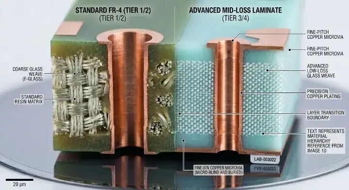
At these speeds, the physical woven fiberglass inside the board becomes a severe hazard. The IPC-4202B specification defines standard glass weave types (like 106, 1080, and 2116). For 25+ Gbps signals, routing a trace directly over a glass bundle versus the resin gap creates massive glass weave skew. You must select Ultra-Low-Loss materials utilizing spread-glass or mechanically flattened weaves to maintain timing budgets.
Users on the All About Circuits forum commonly ask: “Why does my Ultra-Low-Loss board cost 6x standard? Is this normal or is my fab gouging me?” A 6x markup is completely normal for this tier. The cost structure breaks down into three specific drivers:
- The raw material unit price is inherently 200-400% higher.
- Lamination yield risk adds another 10-15% to the cost.
- Process equipment depreciation (running custom press cycles) adds 30%.
- If your volume is low (<100 pcs), costs hit 7-8x. You only compress pricing down to 5-6x at production scale (1000+ pcs). Red flag: If a factory quotes you only a 3-4x multiplier for an Ultra-Low-Loss board, they are likely using a cheaper Low-Loss substitute. You must demand the exact material model in the RFQ.
Here is the reality on the factory floor: On our HDI line, the most expensive material we routinely process is Panasonic Megtron 7—Dk 3.3, Df 0.002 at 10 GHz. The prepreg has notoriously poor flow during lamination compared to standard FR-4. We run a custom press profile with a 30°C lower peak temperature and a 40% longer cooling ramp to prevent resin starvation between layers. Even with the optimized profile, our first-pass yield on Megtron 7 boards averages 96.8% versus 99.5% on standard FR-4. The yield gap is real and unavoidable—it shows up in our quoting. When customers see Ultra-Low-Loss quotes at 5-8× standard PCB pricing and assume we are upcharging, we share this yield data. It is the actual process cost. Smaller fabs that quote 3-4× for Ultra-Low-Loss are almost always quoting Low-Loss substrates relabeled as the higher grade.
Bottom line: Specify exact Ultra-Low-Loss models like Megtron 7 or Astra MT77 for 25+ Gbps boards, and accept the 5-8x cost multiplier as a reality of complex lamination yields.
7. When Do You Actually Need RF / Microwave-Grade Materials?
You strictly need RF or Microwave-Grade materials when operating in the 5G mmWave bands (24/28/39 GHz) or designing radar systems, requiring ceramic-filled substrates that cost 6-10x more than standard FR-4. These boards are not defined purely by low loss; they are defined by a Dk that remains completely flat and stable across massive temperature and frequency shifts.
You will find these properties in:
- Antenna substrates requiring zero phase shift.
- Satellite communication arrays.
- High-frequency automotive radar modules.
These ceramic-filled systems, such as Rogers RO4350B, Rogers RO4003C, Taconic RF-35, and Arlon AD250C, possess entirely different mechanical behaviors than traditional epoxy resins. They are harder on drill bits and require highly specialized surface preparation for plating.
Bottom line: Purchase RF-Grade materials only when your design relies on precise phase control at microwave frequencies, as the 6-10x cost multiplier is impossible to justify for standard digital routing.
8. How Does HDI PCB Material Selection Affect Cost and Lead Time?
Material selection affects cost and lead time by simultaneously increasing the base laminate price, extending supply chain wait times up to 28 days, and drastically reducing lamination yield rates in the press. The raw laminate only dictates 30-40% of the final unit cost; the actual expense comes from the severe difficulty of bonding advanced low-loss prepregs.
On EEVBlog, a common complaint arises: “What is the actual cost difference between Megtron 6 and standard FR-4 high-Tg? My fab quotes are wildly inconsistent. Trying to understand if I am being upcharged.” The 3-4x cost multiplier for Megtron 6 is accurate. The inconsistent quotes exist because different factories possess different processing capabilities.
- A factory quoting $5 per unit for standard FR-4 and $15-20 per unit for Megtron 6 is providing a fair, realistic price.
- Small fabs offering suspiciously tight margins are a massive red flag—they likely lack the process controls to bond Megtron 6 reliably and are substituting substandard materials.
- Always force the fab to list the exact material model, core thickness, copper weight, and estimated yield assumptions in the final quote.
Material choices heavily dictate your lead times as well. Standard FR-4 materials are stocked natively, allowing 7-10 day turns. Mid-Loss and Low-Loss laminates push schedules to 14-18 days. Ultra-Low-Loss substrates often suffer from supply chain shortages, requiring 21-28 days just to procure the laminate. To offset these costs, you should review strategies to reduce HDI lamination cost directly in your stackup geometry.
Bottom line: Plan for a 3-4x cost multiplier and a 3-week lead time minimum when transitioning your stackup away from standard FR-4 to advanced low-loss laminates.
9. How Do You Specify HDI Material in Your Fabrication RFQ?
You specify HDI material in your RFQ by explicitly listing the material brand, exact Dk/Df values at your specific operating frequency, core thickness in mils, and copper weights for every single layer. Leaving material choices as “Low-Loss equivalent” invites factories to swap in cheaper, lower-tier materials that will destroy your impedance targets.
When building your stackup, verify that your chosen materials can actually be processed together. If you are mixing standard rigid laminates with high-end RF substrates, you must track the CTE differences. Certain signals that need HDI design rules will fail if you mix mechanically incompatible cores.
Table 4: Mixed Material Build-up Viability Matrix
| Base Material (Core) | Mixed with (Prepreg/Outer) | Z-Axis CTE Mismatch | Viability & Yield Impact |
|---|---|---|---|
| FR-4 Standard | FR-4 Standard | None | Excellent (99% Yield) |
| FR-4 High-Tg | Mid-Loss (e.g., IS415) | Low (< 30 ppm) | High (98% Yield) |
| Low-Loss (Megtron 4) | Ultra-Low-Loss (Megtron 7) | Moderate (30-50 ppm) | Fair (Requires custom profile) |
| Standard FR-4 | RF-Grade (Rogers 4350) | Extreme (~200 ppm) | Poor (5-10% Yield drop, risky) |
Mix standard FR-4 with Mid-Loss if you need mild upgrades. Avoid mixing RF-Grade ceramic laminates directly with Standard FR-4 unless you can tolerate significant yield drops.
To protect your layout, demand cross-section samples from your fab’s prior runs using the identical laminate. For complex builds, you should leverage controlled impedance PCB design rules and specify the exact glass weave style (like spread-glass 1078) to eliminate skew risks outright.
Bottom line: Document the exact material grade, core thickness, and target frequency directly in your RFQ to block unauthorized factory substitutions.
Choosing the correct HDI PCB material dictates whether your high-speed signals survive or collapse, directly establishing your total manufacturing cost. By matching your trace length and frequency budget to a specific 5-category material framework, you eliminate guesswork and stop overpaying for unnecessary ultra-low-loss upgrades.
At QueenEMS, we routinely process everything from standard high-Tg consumer boards to strict Megtron 7 server backplanes. We run custom press profiles specifically engineered for advanced low-loss prepregs to protect your first-pass yields. If you are struggling to map your insertion loss budget to the right laminate category, reach out to our engineering team to request an engineering quote and full DFM stackup review today.
Written by the QueenEMS Engineering Team
Frequently Asked Questions
What HDI material do I need for 10 Gbps signals? It depends heavily on your trace length. For traces under 6 inches, a Mid-Loss laminate (Df ~0.010) works perfectly. For traces 6-12 inches, you must step up to Low-Loss (Df ~0.005) to keep insertion loss under your 8-10 dB budget. Over 12 inches, even 10 Gbps may need Ultra-Low-Loss plus equalization. Calculate total IL = trace length × loss per inch and compare it against your budget. Send your layout for an engineering review to confirm your exact margins.
Can I mix Rogers and FR-4 in the same HDI stackup? Yes, but with severe mechanical constraints. The massive CTE mismatch (Rogers z-axis ~50 ppm versus FR-4 ~250 ppm) places heavy stress on microvias during thermal cycling. Your factory yield will drop 5-10% versus same-material stacks, and lamination requires a difficult hybrid press profile. It is often cheaper to use Rogers for all RF layers in a separate board interconnected via flex, or use ceramic-filled FR-4 as a compromise.
Why does Ultra-Low-Loss HDI cost 6x more than standard? Ultra-Low-Loss boards cost 6x more because of three compounding factors: the material unit cost is 3-5x higher; lamination yield runs at 96-97% versus 99.5% for FR-4 due to extremely poor prepreg flow; and material lead times stretch to 8-12 weeks, complicating supply chain pricing. Any quote below a 5x multiplier is a major red flag indicating a likely substitute material being passed off as the higher grade. Always demand full material certs before mass production.
How do I specify HDI material in my RFQ? You specify it by clearly writing four data points: (1) exact material brand and grade (e.g., “Megtron 6 N4000-13EP”), (2) specific thickness in mils or microns, (3) exact copper weight on each individual layer, and (4) target Dk/Df values at your operating frequency. Request the estimated first-pass yield explicitly in the quote. Always ask the fab to provide cross-section sample images from prior projects using that exact same material.
Is upgrading to Ultra-Low-Loss worth future-proofing? Usually, no. Future-proofing by jumping two material categories adds 50-100% to your total board cost but rarely matches future needs; when you actually upgrade to higher speeds later, you will redesign the entire stackup anyway. A better strategy is to match your material strictly to your current signal needs while keeping a 20% insertion loss budget margin. Run precise simulations based on current hardware, not hypothetical future processors.