
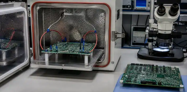
Quick Answer: PCB CAF prevention requires all three parts of the failure chain to be controlled: a vulnerable path inside the laminate, moisture and ionic activity, and electrical bias between conductors. Reduce risk through spacing and voltage review, CAF-resistant laminate selection, drilling and lamination controls, cleanliness and moisture management, plus temperature-humidity-bias testing on a coupon that represents the real geometry.
Key takeaways – CAF is an internal electrochemical migration failure, not ordinary surface contamination. – Via-to-via spacing must be reviewed with drilled diameters, glass direction, voltage, material, and process damage. – A datasheet claim of “CAF resistant” needs a test method, construction, and result relevant to the product. – A production electrical test can find shorts today; it does not qualify years of humid biased service.
PCB CAF prevention becomes an RFQ issue when dense plated holes, sustained DC bias, humidity, long field life, high voltage, repeated thermal cycling, or safety consequences appear in the same product. Conductive anodic filamentation can develop inside the glass-resin structure, so a clean visual inspection and a passing room-temperature bare-board electrical test do not close the reliability question.
This article focuses on preventing and qualifying CAF risk before production. It does not replace the broader high-voltage PCB spacing requirements or the separate ionic cleanliness test review. Those pages own external spacing and surface-residue decisions; CAF adds internal pathways, laminate interfaces, drilled features, moisture, and bias duration.
Table of Contents
- Recognize the CAF failure mechanism
- Screen the layout for vulnerable geometry
- Select laminate from test evidence
- Control fabrication and environmental contributors
- Build a representative CAF test plan
- Investigate suspected field failures
- Put CAF controls into the RFQ
Recognize the CAF failure mechanism
CAF develops when copper-containing conductive material grows along a susceptible internal path between oppositely biased conductors. The path commonly follows a damaged or degraded glass-fibre-to-resin interface, while moisture supplies an electrolyte and voltage drives the electrochemical process.
This mechanism differs from dendritic growth across a contaminated board surface. Surface insulation resistance testing and cleaning controls can reveal external migration risk, but CAF can remain hidden within the laminate. Conformal coating may reduce moisture reaching the assembly surface, yet it does not repair an internal resin-glass separation already present in the board.
Several events can create or worsen the pathway: drilling microdamage near glass bundles, poor silane interface durability, resin starvation, voids, incomplete wetting during lamination, thermal expansion mismatch, excessive process heat, or chemical attack. The path alone is still not enough; humidity and electrical potential complete the failure conditions.
The observable symptom may be intermittent leakage, insulation resistance decay, or a hard short after environmental exposure. A room-temperature retest can miss a failure that changes with humidity. Product teams should preserve bias polarity, environmental history, and board location when a suspected short is first found.
Decision rule: A credible CAF review identifies pathway, moisture, and bias; controlling only one without evidence leaves the mechanism open.
Screen the layout for vulnerable geometry
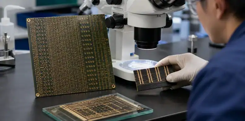
Layout screening should begin with drilled-hole wall spacing between nets at different potentials, then extend to hole-to-plane, trace-to-trace, layer-to-layer, and microvia structures that may create a short internal path.
Use drilled diameter rather than only finished-hole diameter when assessing adjacent plated through holes. The drilled wall defines the laminate left between holes before plating, and fabrication tolerances can reduce the actual separation. Include layer registration, drill wander, artwork scaling, and the closest glass-fibre orientation rather than relying on nominal CAD centres.
Voltage changes the electric field across a given separation. A low-voltage dense digital design and a high-voltage control board can share identical geometry but have different field reliability. Record normal, maximum, transient, and test bias where they affect the qualification. Polarity also matters during failure analysis because CAF growth follows an electrochemical direction.
Glass weave orientation can make apparently equal spacings behave differently. Rows of holes aligned with fibre bundles may present a continuous interface, which is one reason standard CAF coupon designs include specific orientations and staggered patterns. Rotate or relocate sensitive via arrays only after signal integrity, routing, and manufacturability are reviewed together.
| Geometry input | Why nominal spacing is incomplete |
|---|---|
| Drill diameter and tolerance | Determines remaining resin-glass distance |
| Net-to-net bias | Sets electrical stress across that distance |
| Fibre direction | Changes available internal pathway |
| Layer registration | Can move copper closer than CAD centres show |
| Thermal cycle count | May enlarge interface damage before service |
For dense multilayers, carry this screen into the supplier stack-up review so the same critical hole arrays are evaluated during material construction and drill planning.
Select laminate from test evidence
Choose a CAF-resistant laminate by matching documented test performance to the product’s voltage, spacing, temperature, humidity, construction, and service objective. A marketing label without coupon geometry or conditioning cannot establish product reliability.
Review the laminate datasheet, IPC-4101 slash-sheet designation where applicable, resin system, glass styles, resin content, moisture absorption data, thermal properties, and the manufacturer’s CAF test method. Ask which hole spacings, bias levels, temperature, relative humidity, duration, and failure threshold were used. A result on a generous test pattern may not represent a dense via field.
Material qualification must also survive fabrication. A resin system with good laboratory CAF performance can lose margin if the construction creates resin-starved areas or if drilling and desmear damage the interface. Core and prepreg choices, glass styles, copper weights, pressed thickness, and lamination cycles belong in the approved stack-up.
Do not permit an unreviewed “equivalent FR-4” substitution. The substitute may match Tg and dielectric constant while carrying different moisture, glass treatment, resin flow, or CAF data. Route any proposal through supplier stack-up signoff and the PCB material substitution approval process.
A useful material comparison records the exact grade, construction, CAF method, test conditions, failure criterion, source document revision, and gaps. Engineering can then decide whether a coupon or first-article qualification is required.
Acceptance rule: Accept the grade and construction that own the relevant CAF evidence; Tg matching alone is not equivalence.
Control fabrication and environmental contributors
Fabrication controls should minimise glass-resin damage around holes and avoid weak interfaces during lamination. Drill condition, feed and speed, hit count, entry and backup materials, hole aspect ratio, cleaning, desmear, plasma or chemistry compatibility, resin flow, press cycle, and moisture before lamination can all influence the pathway.
The buyer should not prescribe proprietary machine parameters without process knowledge. Instead, identify the sensitive features and require the supplier to confirm a qualified route. Critical via fields, minimum drilled-wall spacing, sequential lamination, resin-starved copper patterns, press-fit arrays, and high-temperature assembly should be visible during CAM review.
Microsection evidence can reveal smear, resin recession, voiding, plating condition, glass fracture, and local construction, but the coupon location must represent the risk. A section from a generous panel corner does not necessarily prove the dense biased array. The PCB microsection report requirements page explains lot identity and report fields; a CAF-focused plan adds feature location and pathway relevance.
Process changes deserve renewed review. A material supplier change, drill diameter reduction, different glass style, new desmear chemistry, added press cycle, or relocated fabrication site can alter the qualification basis even when the part number remains unchanged.
Process gate: The fabricator owns its recipe, but engineering owns whether the qualified recipe represents the released high-risk geometry.
Moisture management reduces the electrolyte available for CAF, while ionic control limits species that support electrochemical migration. These controls begin with laminate storage and lamination preparation and continue through fabrication, assembly, cleaning, coating, enclosure design, and field exposure.
Prepreg and cores should be stored and handled according to the material supplier’s instructions. Excess moisture before pressing can affect laminate quality, and poor drying or storage discipline may weaken the finished structure. The bare-board supplier should control rinsing and process residues without presenting a single cleanliness result as proof of internal CAF immunity.
Assembly adds fluxes, cleaning chemistry, wash water, conformal coating, and thermal cycles. Surface residues can create separate electrochemical migration paths and may complicate failure analysis. Define ionic-cleanliness or surface-insulation-resistance controls where product risk requires them, while keeping the CAF coupon qualification distinct.
The product enclosure determines environmental exposure. Condensation, high relative humidity, polluted air, salt, pressure cycling, or repeated warm-cold transitions can drive moisture into an assembly despite acceptable warehouse storage. System-level humidity testing may be necessary in addition to laminate qualification.
Baking can reduce moisture before assembly, but it does not restore glass-resin bonding or remove all internal ionic contributors. An arbitrary bake should not be described as CAF prevention. Treat it as one controlled step within a material and process plan.
Environment rule: Moisture control lowers probability, but it cannot compensate for marginal spacing or damaged laminate interfaces.
Build a representative CAF test plan
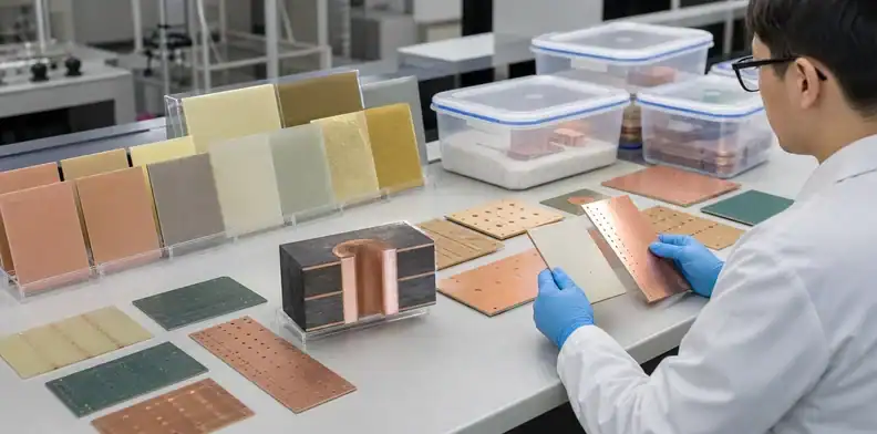
A CAF test plan should reproduce the conductor orientation, spacing, material construction, fabrication route, conditioning, humidity, temperature, bias, monitoring, duration, and failure threshold relevant to the product decision.
IPC-TM-650 Method 2.6.25 provides a recognised approach for conductive anodic filament resistance testing in the X-Y axis. IPC-9691B explains implementation considerations and the need to connect pass/fail criteria with product goals. Standard coupon families evaluate defined hole relationships and can support material or process comparison.
Do not copy an 85°C/85% RH slogan into the RFQ and assume the qualification is complete. The named method may use specific conditions, sample quantities, preconditioning, voltage, monitoring, and coupon geometry. Product tests sometimes use different conditions for a justified reason. Record the exact method revision and deviations.
Test ownership should be explicit. The laminate manufacturer may supply comparative data, the board fabricator may build qualified coupons, an independent laboratory may run the chamber, and the OEM may define the failure threshold. The report must connect those parties through sample identity and chain of custody.
| Test-plan field | Decision it supports |
|---|---|
| Coupon construction and hole pattern | Represents the board’s vulnerable geometry |
| Material grade and fabrication lot | Links results to production inputs |
| Preconditioning | Accounts for thermal or moisture history |
| Temperature, RH, and bias | Defines applied environmental stress |
| Monitoring interval and threshold | Shows when insulation resistance changes |
| Duration and sample count | Establishes qualification confidence |
The test result should report individual failures and time behaviour, not only a final pass label. A sudden short and gradual resistance decay can guide different investigations.
Acceptance rule: Coupon data is transferable only when material, construction, process, and stress remain inside the approved boundary.
Investigate suspected field failures
Suspected CAF failures require environmental reproduction, electrical localisation, and careful physical analysis. Cutting the board too early can destroy the filament or remove the relationship between polarity, moisture, and the internal path.
Preserve the failed state where practical. Record product serial number, PCB lot, operating voltage, polarity, service time, temperature and humidity history, cleaning and coating status, and whether the fault disappears when dry. Map the resistance between nets and compare failed, adjacent, and unaffected boards.
Non-destructive techniques may narrow the location before cross-sectioning. Electrical monitoring under controlled humidity can reproduce leakage. X-ray or computed tomography may reveal structural context but may not directly show a fine conductive filament. Dye, scanning electron microscopy, energy-dispersive X-ray analysis, or targeted microsections can support root-cause work when the laboratory selects them appropriately.
Distinguish CAF from surface dendrites, conductive contamination, plating debris, carbonised laminate, conductive anodic growth in another orientation, assembly residue, and component leakage. A copper-containing path near glass fibres supports the hypothesis, but the conclusion should integrate chemical, structural, electrical, and environmental evidence.
Corrective action may involve layout spacing, material grade, glass style, drill process, desmear, lamination moisture, cleaning, coating, enclosure, or qualification testing. Do not close the investigation with “use better FR-4” when the path and trigger remain unidentified.
Proof check: A confirmed mechanism must explain the failed nets, polarity, internal route, environmental trigger, and manufacturing lot evidence.

Put CAF controls into the RFQ
The RFQ should show the fabricator where CAF matters and what qualification or shipment proof is expected. Send the stack-up, material requirement, Gerber or ODB++, drill files, drill chart, controlled impedance information, voltage map for critical nets, closest biased-hole geometry, glass-direction concerns, assembly thermal sequence, and service environment.
Specify the applicable IPC or customer documents, required CAF-resistant material grade or approved alternatives, substitution rule, coupon design, test method and revision, conditions, sample count, threshold, report timing, and approval owner. Separate one-time process qualification from per-lot shipment records so suppliers price the correct work.
A focused note can read:
The identified biased via structures are CAF-sensitive. Build with the approved laminate and stack-up, maintain the released drilled-wall spacing, and use the qualified drilling, desmear, and lamination route. Obtain engineering approval before changing material construction or process location; provide the specified CAF qualification and lot traceability records.
For QueenEMS review, submit the critical-net voltage table, minimum hole-to-hole separations, drill diameters, laminate choices, stack-up, expected temperature-humidity exposure, thermal cycles, and requested IPC-TM-650 coupon evidence through the QueenEMS contact page. The quotation can separate standard fabrication from material qualification, coupon production, laboratory testing, and report delivery.
RFQ outcome: A complete proposal ties the risky geometry to an approved material-process route and a test boundary that engineering can defend. Review our PCB quality control capabilities.
FAQ
Can a 100% electrical test prove a board is CAF safe?
No. It can detect opens and shorts at the test condition, but CAF may develop only after sustained humidity and electrical bias. Reliability qualification needs a representative environmental-bias method.
Is CAF the same as ionic contamination on the PCB surface?
No. CAF forms inside the laminate, commonly along glass-resin interfaces. Surface ionic contamination can cause other migration or leakage mechanisms and should be controlled separately.
Does conformal coating prevent CAF?
Not by itself. Coating may reduce environmental moisture at the assembly surface, but it cannot remove internal fabrication damage or guarantee that moisture never reaches the laminate.
What changes should trigger CAF requalification?
Review material grade or construction, glass style, resin system, drill geometry, spacing, desmear chemistry, lamination cycle, fabrication site, assembly heat, and service voltage changes. Requalification depth depends on how far the change moves outside the approved test boundary.
Sources
- IPC, IPC-TM-650 Method 2.6.25B CAF Resistance Test
- IPC, IPC-9691B User Guide for CAF Resistance Testing
Written by the QueenEMS Engineering Team
Upload your files today · Free DFM check before production · Ship worldwide
Get your PCB prototypes in as fast as 24 hours. We handle FR4, Rogers, and hybrid boards up to 40 layers in volume production, with advanced builds subject to engineering review — free prototypes for 2–4 layer FR-4 boards, no minimum order.
Just upload your Gerber + BOM — we source every part, assemble, and inspect (AOI + X‑Ray) so you don't have to chase suppliers. Boards ship in as fast as 24 hours.