
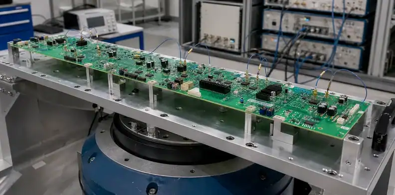
Quick Answer: Large PCB vibration testing is representative only when the profile, production mounting, shaker fixture, control channels and board-response measurements describe the same installed product. Find resonance at low level, monitor the long spans and vulnerable interconnects, define interruption rules before the run, and compare electrical plus physical evidence before and after every required exposure.
A vibration test can misrepresent a large PCB assembly when the test article is mechanically different from the fielded product. A long populated board mounted at a few edge points can amplify motion between supports, while a rigid laboratory plate can suppress that response. The report needs to connect the service requirement and mounting configuration to the measured input, board response and acceptance evidence.
The test plan needs to reproduce the mounting and support conditions of the intended assembly. Review the large PCB support and stiffener options before freezing that configuration. Then specify the vibration input, measured board response and acceptance evidence for the application; there is no single set of test values suitable for every product.
Table of Contents
- Define the vibration input from service evidence
- Reproduce the installed mounting boundary
- Locate board modes before the qualification run
- Separate input control from board response
- Monitor seven large PCB vibration testing failure risks
- Freeze the sequence and interruption rules
- Inspect and electrically verify after exposure
- Build a test-ready RFQ and evidence package
Define the vibration input from service evidence
Begin with the product environment, not a convenient laboratory profile. Identify where the assembly operates, how the enclosure is attached, which axes carry continuous vibration, whether transportation is a separate condition, and what customer or program document controls the test. A test lab can implement a released profile; it should not be forced to guess what the product must survive.
Government and standards-body examples show why scope matters. Caltrans ties vehicle-electronics vibration requirements to installation, while ECSS requires project levels and representative mounting. These are process examples, not universal numeric limits.
Separate the service environment from the test profile
Service evidence may start as measured field data, a customer specification, a system-level requirement or a referenced industry standard. Convert it into an approved laboratory instruction that names axes, input type, frequency content, severity, duration, tolerances and any preconditioning. Preserve the source and the engineer who approved the translation.
Do not mix sine survey, sine qualification, random vibration and mechanical shock under one vague “vibration test” label. They answer different questions. A low-level survey locates modes; a qualification exposure applies the released environment; shock addresses a transient event. If the PO requires more than one, list each as its own stage and acceptance gate.
Freeze the operating state and monitored functions
Decide whether the assembly is unpowered, powered but idle, or operating under a representative load. Define supplies, harnesses, loads, cooling, software state and communication traffic. The operating state can change mass distribution, cable restraint, heat and the electrical faults that can be observed.
Select monitored functions before fixture design. Intermittent connector contact, relay chatter, reset, communication dropout, resistance change or sensor discontinuity may last too briefly for a post-test functional check to find. Name the channels, sample or event-capture method, allowable interruption and data owner in the test plan.
| Input decision | Required record | Approval owner |
|---|---|---|
| Service environment | Location, source requirement and field-data basis | Customer or product engineering |
| Laboratory profile | Axis, input type, frequency content, duration and tolerance | Test authority |
| Operating state | Power, loads, cooling, software and harness configuration | Electrical/system engineering |
| Functional monitoring | Channels, sampling, event limits and timestamps | Quality plus test engineering |
Release point: Do not book the qualification run until the requirement source, translated profile, operating state and monitored functions have named owners.
Reproduce the installed mounting boundary
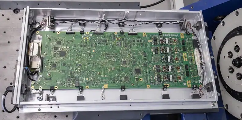
The board should see its service constraints. Use the production enclosure or a qualified surrogate that reproduces standoffs, edge guides, fasteners, stiffeners, backplates, connector brackets and cable restraint. Record every deviation. A perimeter-clamped PCB does not represent a product held by internal standoffs.
Large boards make boundary errors expensive because unsupported length and attached mass strongly influence dynamic response. A fixture that adds support under the center may reduce displacement around a heavy connector. Removing a production brace can create a failure that the installed assembly would never experience. Neither result describes the product unless the deviation was intentional and approved.
Match production constraints and fasteners
Build a mounting drawing that identifies fixed and slotted holes, fastener type, washer, torque, locking method, standoff height, local bracket contact and permitted gaps. Include the populated mass, center of gravity, heavy-component locations and harness attachment points. Use production hardware where practical and record the actual torque or installation evidence.
Check for bottomed fasteners, incomplete seating, loose inserts and fixture interference. A screw can feel tight while reaching the end of a hole before the joint clamps.
Keep the fixture outside the product response
The shaker fixture must transmit the commanded input without adding a dominant mode, excessive cross-axis motion or local flexibility inside the measurement band. Review fixture material, load path, bolt pattern, mass and orientation with the test laboratory. Measure the fixture response rather than declaring it rigid from CAD alone.
If the fixture amplifies input at a frequency of interest, change or justify it before interpreting board response. Do not correct away a production-enclosure response that belongs to the installed product.
Use the large PCB connector-alignment workflow when connectors, rails or chassis datums govern installation. The same datum logic should appear in the test mounting drawing and the post-test inspection.
Decision point: Approve the setup only when its restraints and load paths match the released production boundary or an explicitly accepted surrogate.
Locate board modes before the qualification run
A low-level modal or resonance survey can reveal where the assembly amplifies the fixture input before the damaging exposure begins. ECSS board-verification guidance, for example, calls for detecting primary resonance and recording transfer behavior. The exact survey levels and frequency range remain project-specific; the transferable lesson is to find the response before applying the full requirement.
For a large PCB, expect more than one relevant response. An enclosure mode, a long board-span mode, a heat-sink bracket mode and a connector/cable mode can appear in the same axis. The test plan should state which responses are monitored and what comparison decides whether the setup is safe to continue.
Use a low-level survey to locate resonance
Run the approved low-level input in each required orientation and calculate or plot the relationship between fixture input and response channels. Record peak frequencies, phase or transmissibility information used by the test authority, and the physical locations associated with them. Repeat the survey after the exposure when the governing plan requires a before/after comparison.
A frequency shift is evidence to investigate, not a universal failure threshold. Define the comparison method and disposition before testing.
Compare input and response at long spans
Place response measurements at credible high-deflection regions, often between supports rather than directly beside a rigid standoff. Heavy components, tall connectors and board cutouts can redirect strain, so combine the mechanical drawing, simple analysis and first survey results. If a sensor location changes after the survey, document why and retain both channel maps.
Natural frequency depends on geometry, material, mass and support. Do not reuse a resonance prediction from a small coupon or an unpopulated board as final evidence for a populated oversized assembly. A model may guide sensor placement, but the representative mounted hardware closes the test decision.
Decision point: Hold the high-level run if an anomaly or loose boundary prevents the team from separating product behavior from setup behavior.
Separate input control from board response
The control channel tells the shaker system what input reaches the controlled interface. Response channels tell engineering how the fixture, enclosure and board react. Treating one accelerometer on the shaker table as proof of board loading can miss fixture amplification, attenuation or cross-axis motion.
ECSS guidance distinguishes input measured at the vibration interface from response measured on the assembled PCB and base plate. Channel count and placement must still follow the actual assembly and available equipment.
Choose control and response locations
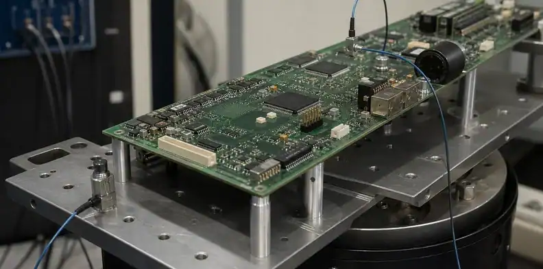
Locate control sensors at the agreed fixture/product interface and distribute them where the test authority can detect nonuniform input. Put response sensors on the board, enclosure or component bracket at locations tied to a risk hypothesis. Give each channel a unique ID, axis arrow, coordinate, mounting method and photograph.
Avoid placing every board sensor next to supports merely because access is easy. A central long span, heavy transformer footprint, connector corner or large BGA region may be more informative. If component access prevents a direct measurement, document the surrogate point and the limitation.
Limit sensor and cable influence
An accelerometer, adhesive base and cable add mass and stiffness to the measured structure. PCB Piezotronics notes that mounting technique and added interface mass change the mounted resonance and usable frequency response. On a thin or flexible board, use a sensor and attachment method whose influence is acceptable for the required measurement range.
Route cables so they do not brace the board, pull on the sensor or strike adjacent hardware. Provide strain relief outside the sensitive span and check clearance in all axes. Preserve calibration identity, orientation, mounting preparation and any channel substitution in the final report.
| Channel role | Preferred evidence | Common misleading setup |
|---|---|---|
| Shaker/fixture control | Interface location, orientation and control record | One remote table sensor assumed to represent the product |
| Fixture response | Transfer behavior and cross-axis review | Fixture resonance mistaken for a product mode |
| Board response | Risk-based span or component location | All sensors clustered near rigid supports |
| Electrical monitor | Timestamped continuity or functional log | Only a post-test power-on check |
Evidence check: A control-channel trace records measured motion at its sensor location; the commanded profile is the target the control system is trying to achieve. Neither value alone describes motion across the PCB.
Preserve the command, measured control, board-response and functional logs on a synchronized time base. An electrical interruption can then be checked against actual excitation and local response, rather than assigned to the nominal test level alone. NASA’s vibration-testing guidance distinguishes measurements near structural interfaces from those at predicted high-response locations. Use that measurement principle while selecting positions, test levels and acceptance limits for the approved product-specific plan; spacecraft test levels are not general PCB limits.
Monitor seven large PCB vibration testing failure risks
The numbered headline refers to seven distinct failures that a representative plan can prevent or expose. Assign each risk a location, monitoring method and acceptance record. Do not depend on one global accelerometer or one final visual inspection to close all seven.
| Failure risk | Why a large assembly is exposed | Evidence that closes the risk |
|---|---|---|
| 1. Long-span resonance | Greater distance between supports can amplify local motion | Input-to-response data plus documented span locations |
| 2. Heavy-component load | Transformers, heat sinks and large capacitors add inertia | Bracket/lead inspection, local response and retention check |
| 3. Connector intermittency | Tall connectors and harnesses apply leverage at joints | Functional or continuity monitoring with event timestamps |
| 4. Solder-joint fatigue or cracking | Repeated board curvature loads component terminations | Pre/post electrical checks and targeted optical or X-ray evidence |
| 5. Fastener or standoff loosening | Large interfaces use more mounting points and tolerance stack | Torque/position evidence and post-test movement inspection |
| 6. Fixture-induced false result | A flexible or over-supporting fixture changes the product response | Fixture survey and explicit production-boundary comparison |
| 7. Sensor-induced measurement error | Sensor/cable mass can alter a thin span or filter response | Mounting review, calibration record and cable-control photographs |
Prioritize locations before the test vehicle is built. For a tall heat sink, state whether the concern is loose hardware, lead strain, board curvature or enclosure contact; each needs different evidence.
Continuity monitoring is especially valuable where a brief open can recover before the axis ends. Provide dedicated loops, test points or representative functional traffic when the design allows. If continuous monitoring is unavailable, state the limitation and strengthen stop-point functional checks rather than implying uninterrupted coverage.
Use large PCB inspection planning to align photographs, dimensional records and targeted imaging with the assembly serial number. Vibration evidence should be traceable to the exact board, fixture revision, orientation and channel map.
Freeze the sequence and interruption rules
A controlled sequence protects both the hardware and the meaning of the data. Start with receiving condition, mounting verification, baseline electrical/functional results, sensor installation and a low-level survey. Then execute approved exposures and stop-point checks in the specified axes. End with the required repeat survey, inspection, functional test and engineering disposition.
Define an interruption before the shaker starts. Examples include loss of a monitored function beyond the approved event limit, fixture or control-channel anomaly, unexpected noise or contact, excessive response under the test authority’s criterion, loose hardware, sensor loss or inability to maintain the commanded input. The plan must name who can stop, who can authorize restart and what evidence is preserved.
| Stage | Minimum record | Hold condition |
|---|---|---|
| Pre-test baseline | Serial, configuration, photos, torque and functional result | Wrong revision, damaged hardware or incomplete mounting |
| Low-level survey | Control/response plots and channel map | Unexplained fixture or product response |
| Each exposure/axis | Input, response, monitoring log and event timestamps | Limit event, sensor fault or setup change |
| Stop-point check | Visual, hardware and functional result | New defect or unresolved intermittent fault |
| Final disposition | Before/after comparison and approvals | Missing evidence or failed acceptance criterion |
Do not erase a failed start by remounting and rerunning. Record configuration, interruption, suspected cause, inspection, correction and authorization. Change one variable at a time where practical and decide whether completed exposure remains valid.
Decision point: A clean end-of-run plot does not override an unexplained interruption or missing functional log.
Inspect and electrically verify after exposure
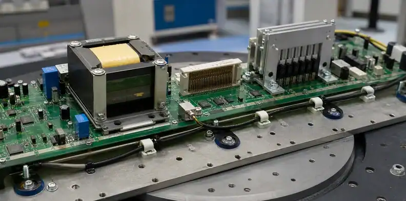
Post-test verification should compare against the pre-test baseline, not against memory. Inspect mounting points, standoffs, brackets, connector shells, cable restraints, heavy components, board edges, cutouts and high-response regions. Look for looseness, fretting, cracked coating, displaced hardware, board contact and evidence of component movement.
Use magnification and targeted imaging where the risk justifies it. Optical inspection can find visible cracking or movement, while X-ray may help evaluate hidden joints; neither substitutes for functional or continuity data. If destructive sectioning is required, plan a designated sample and acceptance method before the test.
Repeat the approved electrical and functional checks with the same loads, harnesses, software and limits used for the baseline. Reconcile monitoring events with physical locations and shaker timestamps. A recovered communication dropout may still be a failure under the governing criterion.
Review before/after modal data when required. A changed peak or transfer relationship should trigger a check of fasteners, sensors, cables and structure before attributing damage. Engineering owns that interpretation; a production inspector should not be asked to invent a numeric frequency-shift limit.
Create one evidence package containing:
- article and assembly serial numbers plus revision;
- mounting and fixture drawings with actual configuration photographs;
- sensor/channel map, calibration identity and cable routing;
- commanded and measured input records;
- board-response plots and functional-monitoring events;
- interruption, restart and deviation records;
- pre/post inspection, electrical and functional results;
- final disposition and approver.
Feed accepted findings back into the large PCB first-article release and production traveler. If a bracket, torque, adhesive or cable restraint becomes necessary for passing performance, it is part of the controlled product configuration.
Build a test-ready RFQ and evidence package
A representative quotation needs visible mechanical and test boundaries. Send finished dimensions, thickness, populated mass, height map, assembly/3D data, mounting drawing, fasteners, heavy-component list, harness configuration, service requirement and qualification stage.
Also state the operating mode, monitored functions, available test points, acceptance source, required axes, any customer-supplied profile, test-article quantity and report format. Identify whether the production enclosure is supplied, whether a surrogate must be designed, and which deviations require customer approval.
Ask the supplier or test laboratory to return:
- the proposed mounting and fixture concept;
- fixture and test-article mass/capacity review;
- control and response channel plan;
- low-level survey and high-level sequence;
- powered-state, harness and cooling arrangement;
- interruption and restart authority;
- pre/post inspection and electrical evidence;
- assumptions, exclusions, lead time and one-time tooling cost.
Do not accept a quotation that promises compliance without naming the requirement, configuration and evidence. QueenEMS can review fabrication and assembly risks, but the customer and qualified test authority retain ownership of the service profile and final compliance decision.
Use the Large Format PCB manufacturing page to align board/assembly feasibility with the test article. Then send board size and mass, mounting drawing, component map, service requirement, operating state, monitoring channels and acceptance criteria through QueenEMS contact. Request a large-PCBA manufacturability and vibration-evidence-plan review before committing tooling or qualification samples.

FAQ
Does a large PCB need a special vibration profile?
Not simply because it is large. The profile comes from the service environment and governing requirement. Size changes the mechanical response, mounting risk, fixture design and number of useful measurement locations.
Should large PCB vibration testing use the production enclosure?
Use it when it is part of the installed load path and a representative article is available. A surrogate can be valid if it reproduces the approved interfaces and its differences are documented and accepted.
Where should an accelerometer be placed on a long PCB?
Place response sensors at risk-based locations such as long spans, heavy-component regions or connector areas, while control sensors measure the agreed interface. Final placement follows analysis, access, sensor influence and the low-level survey.
Must the PCBA be powered during vibration testing?
Only when the requirement and safety plan call for it. Powered monitoring can reveal brief resets, opens or communication loss, but the load, cooling, harness, software state and event criteria must be controlled.
What is the most common false pass?
A nonrepresentative rigid fixture can over-support the board and suppress field-relevant motion. The opposite problem—a flexible fixture adding resonance—can create a false failure. Survey and document the complete boundary.
Sources
- ECSS-Q-ST-70-61C: High-Reliability Assembly Verification
- Caltrans Printed Circuit Board Environmental Requirements
Written by the QueenEMS Engineering Team
Upload your files today · Free DFM check before production · Ship worldwide
Get your PCB prototypes in as fast as 24 hours. We handle FR4, Rogers, and hybrid boards up to 40 layers in volume production, with advanced builds subject to engineering review — free prototypes for 2–4 layer FR-4 boards, no minimum order.
Just upload your Gerber + BOM — we source every part, assemble, and inspect (AOI + X‑Ray) so you don't have to chase suppliers. Boards ship in as fast as 24 hours.