
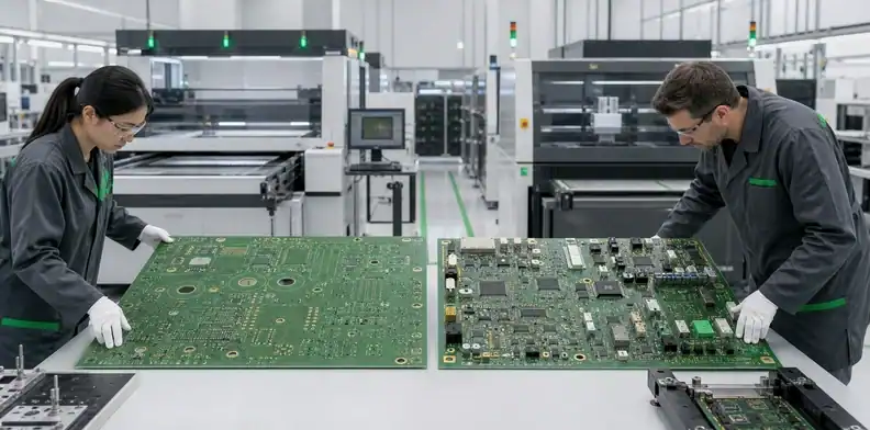
Quick Answer: PCB assembly maximum size depends on a loaded-board envelope and orientation that every required production step can accept. Check the stencil printer, placement machine, reflow conveyor, inspection and test fixtures—not only bare-board fabrication. Release the outline only after one route matrix confirms orientation, carrier, thickness, weight and clearance at every required station.
A quoted bare board can create false confidence. Fabrication may accept the outline, drill it and complete electrical test, while the selected SMT line cannot register the same board in the printer or carry it through reflow. The resulting redesign arrives late because mechanical CAD, enclosure interfaces and connector positions already depend on the original outline.
This article compares the route windows that decide whether an oversized design can become a finished PCBA. The broader maximum PCB size decision explains fabrication limits by layer count and material; the large-format assembly equipment review explains individual SMT operations. Here, the output is different: one controlled bottleneck matrix that lets engineering decide whether to keep the outline, change the route or change the product architecture.
Table of Contents
- Define size as a route envelope
- Separate bare-board and assembled conditions
- Check printing and placement before layout release
- Qualify the loaded reflow envelope
- Include inspection, soldering and test
- Evaluate alternate routes without hiding risk
- Release one process-window matrix
- Submit a route-ready quotation package
Define size as a route envelope
A feasible route must satisfy the verified envelope at every mandatory operation. Length and width are only the first two variables; thickness, mass, underside clearance, edge support, component height and travel orientation can reduce the usable window.
Distinguish machine capacity from usable capacity
A published maximum often describes a nominal work area. Usable capacity may be smaller after rails, clamps, tooling margins, camera access, board supports or process fixtures occupy part of that area. Board capacity and process coverage must be checked separately.
For example, FRITSCH specifies the printALL210XL for a maximum PCB size of 1240 × 600 mm, a maximum printing area of 1170 × 630 mm and a separate stencil-frame limit. These are specifications for that printer, not QueenEMS line capacity. Compare the board outline with the loading window and the full aperture pattern with the printing window, using the machine’s axis definitions. A board that fits the fixture may still need a revised print route before placement can begin.
Ask for the loaded-board window at the exact operation. The response should name the station, transport direction, supported edges, permitted thickness and mass, component-height limits, required tooling margin and whether the value is standard or an engineered exception. A capability table without these qualifiers cannot release the design.
Treat orientation as part of the measurement
Rotating a rectangular board can solve one machine limit and create another. The printer may accept the long edge in X, while the reflow oven needs that edge parallel to travel for support. AOI camera motion, stencil frame orientation, bottom-side components and connector overhang can also make the rotated condition unusable.
Record length and width as loaded, not only as drawing dimensions. Add a simple outline view with the intended conveyor direction and top/bottom component envelopes. That drawing prevents two suppliers from interpreting the same 600 × 900 mm board in opposite orientations.
Separate bare-board and assembled conditions
Bare-board capability and PCBA capability must be approved as two linked but independent routes. The bare board is governed by material, imaging, lamination, drilling, plating, finishing, routing and electrical-test windows; the populated assembly adds paste printing, component placement, thermal processing, optical access, secondary soldering and functional handling.
The product and tooling must fit every required process window in an executable sequence.
| Route condition | Size-related inputs | Typical hidden constraint | Required evidence |
|---|---|---|---|
| Bare PCB fabrication | Finished outline, production panel, layer count, thickness | Registration or plating uniformity over the working panel | Layer-dependent feasibility response |
| Bare-board test | Outline, probe area, fixture access | Test bed or flying-probe travel | Named test method and coverage |
| SMT printing | Board and stencil dimensions, support map | Frame, clamping and underside support | Printer setup sketch or qualified window |
| Placement | Loaded orientation, component height, fiducials | Rail width, camera reach or multi-pass registration | Program-route review |
| Reflow | Board plus carrier, mass, height, rail contact | Loaded width, center support and thermal mass | Profile-vehicle plan |
| Inspection and test | Feature location, underside access, fixture force | AOI travel, X-ray cabinet or fixture bed | Inspection/test disposition |
The table becomes useful only when the same released revision supplies all rows. Mixing a bare-board outline from one revision with a component-height model from another creates a route that exists only on paper.
Release a size only after every mandatory station confirms its loaded orientation for the same product revision, including any controlled rotation between steps.
Check printing and placement before layout release
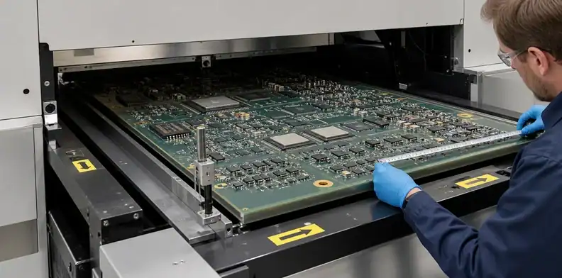
The printer and placement machine frequently set the first practical PCB assembly maximum size because both need repeatable registration and physical support, not merely clearance around the outline. Qualify them while fiducials, tooling strips and component locations can still change.
Printing needs stencil and underside support space
The printer review should cover maximum board size, stencil-frame availability, clamp engagement, squeegee travel, paste-roll clearance and support beneath the active print area. A long board that enters the machine may still deflect under squeegee pressure or lose gasket contact where support pins cannot be placed.
Split printing introduces a second registration event, a boundary between print zones and a longer exposure interval for the first paste deposit. Before including it in the size matrix, review the oversized solder-paste printing process. Record the print boundary, fiducial strategy and solder-paste inspection result as conditions of that route, rather than treating split printing as an automatic extension of machine capacity.
Placement must preserve one coordinate system
A placement machine needs a supported board, visible fiducials and reachable component coordinates. Two placement passes may be possible on some lines, but the second pass must re-establish the same datum without disturbing already placed parts. Board overhang, rail obstruction, nozzle clearance and camera reach can invalidate an apparently sufficient travel number.
Request a placement disposition against the centroid file, component-height model and loaded orientation. The supplier should identify excluded coordinates, manual-placement operations and any required temporary support. Engineering then decides whether those exceptions are acceptable; purchasing should not convert them into an undocumented supplier assumption.
Qualify the loaded reflow envelope
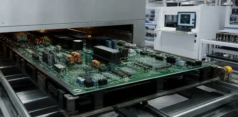
Reflow capacity is determined by the board as it will actually enter the oven, including carrier, retainers, tall components and any center support. A bare-outline comparison understates both width and thermal mass.
Measure the assembly and carrier together
Create a loaded-envelope drawing with carrier outer dimensions, support contact, maximum component height above and below the PCB, conveyor direction and the center of mass. Compare this drawing with entrance, rail, transfer and exit constraints. A carrier may fit the heated chamber yet catch at an upstream handoff or downstream unloader.
Large spans can also require an orientation that keeps the supported edges on the rails. Changing orientation to fit the oven width may leave the long axis unsupported. The large PCB reflow carrier review should be completed before treating carrier dimensions as final.
Size approval does not approve the thermal process
Mechanical passage proves only that the assembly can move through the oven. The populated profile vehicle still needs thermocouples at representative hot, cold and sensitive locations, because a long copper-rich region and a lightly populated edge may not see the same time-temperature history.
Record size qualification and thermal-profile qualification as separate rows. A route may pass the first and fail the second. The correct response is a profile or design review, not a statement that the oven is “large enough.”
Mechanical passage and thermal acceptance require separate records before reflow release.
Include inspection, soldering and test
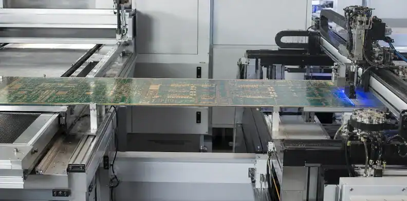
The route is not buildable until post-reflow inspection, secondary assembly and electrical test accept the same loaded product. Late-stage equipment is easy to overlook because suppliers often advertise printer, placement and oven size first.
AOI requires camera travel, focus range, board support and unobstructed access to the inspected side. X-ray adds cabinet and stage limits. Through-hole insertion, wave pallets and selective-solder nozzles add underside clearance, keep-outs and pallet dimensions. In-circuit test distributes probe force across a fixture bed; functional test may need cables, cooling, mating connectors and enclosure references that extend beyond the PCB.
Map every required route step, including outsourced or manual operations. For each one, name the evidence that closes the row: equipment-window confirmation, fixture drawing, inspection coverage map, profile report, test method or approved manual work instruction. “Handled manually” is a method description, not evidence that quality and repeatability are controlled.
The existing large PCB inspection framework helps define flatness, datum, electrical-test and report expectations after the physical route is known. Size qualification should point to that evidence rather than assuming that an inspection label proves full-board coverage.
Evaluate alternate routes without hiding risk
An alternate route is acceptable when its limits, added controls, cost and validation are explicit. It is not acceptable when the quote silently moves work from an automated process to manual handling after the board exceeds a standard window.
Compare exception routes by decision consequence
Common options include a different line, an external specialist, two-stage printing or placement, a custom carrier, selective manual insertion, sectional inspection or a product-architecture change. Each option affects more than cycle time.
| Option | What it may solve | New risk to review | Approval owner |
|---|---|---|---|
| Larger qualified SMT line | Standard single-pass route | Supplier/site dependency | Manufacturing engineering |
| Two-stage operation | Travel limitation at one station | Re-registration and boundary defects | Design plus process engineering |
| Custom carrier or fixture | Support and transport | Added envelope and thermal behavior | Mechanical/process engineering |
| Manual secondary process | Local component or access issue | Repeatability and inspection coverage | Quality and product engineering |
| Split product architecture | Multiple equipment constraints | Connectors, cables, service and system cost | Product owner |
Price the option against the complete route. A lower unit assembly price can be misleading when it excludes carrier NRE, fixture validation, manual inspection, special packaging or additional first-article units.
Hold the quote when the exception is unnamed
The quotation should identify the standard route, every exception and the evidence required before release. A phrase such as “can assemble” is insufficient if no one has confirmed printing, reflow, AOI and test. Put unresolved rows on hold instead of allowing them to become production surprises.
For a contextual route check, send the outline, stack-up, centroid, top/bottom component model and required process list through the QueenEMS DFM review. The useful response is a station-by-station feasibility disposition, not a universal maximum-size promise.
An unnamed manual or two-pass exception remains an open cost and quality risk, not an approved route.
Release one process-window matrix
One controlled matrix should connect the product revision to every manufacturing station and show which row sets PCB assembly maximum size. It becomes the common record for mechanical engineering, PCB layout, sourcing, the fabricator, the assembler and quality.
Use these fields for each station:
- station and site;
- standard or exception route;
- loaded length, width, thickness, mass and height;
- conveyor direction and supported edges;
- tooling, carrier or fixture outer size;
- required input file or drawing revision;
- verification evidence and responsible approver;
- open condition, due date and production hold trigger.
Version the matrix with the PCB and assembly data. A change to board thickness, heatsink height, connector overhang, carrier design or inspection method can move the bottleneck to another station even when the XY outline remains unchanged. Repeat orders should reference the approved matrix instead of relying on a previous supplier memory.
A typical conflict appears when the bare board and printer accept the outline, but the production carrier adds width at reflow or blocks an AOI viewing angle. The matrix should preserve both the product dimension and the loaded tooling dimension. Engineering can then change the carrier, approve another inspection route or reduce the outline without reopening stations that already pass.
Submit a route-ready quotation package
A buildable quotation needs enough information to model both the bare-board and assembled states. Send the released PCB data, mechanical envelope and intended manufacturing route together; otherwise suppliers will price different assumptions.
Include Gerber or ODB++, drill data, stack-up, finished outline and tolerance, board thickness, copper requirements, quantity and panel preference. Add the BOM/AVL, centroid, assembly drawings, 3D component envelopes, fiducials, tooling edges, underside keep-outs, special soldering, inspection coverage and test-fixture needs. State whether alternate lines, two-pass methods or manual operations require written approval.
Send the loaded-envelope drawing, fabrication package, BOM, centroid file, inspection/test scope and expected quantities through the Large Format PCB manufacturing page. Request a quotation that identifies the limiting station, required carrier or fixture, exception operations and the evidence needed for production release.
FAQ
Can a fabricable PCB be too large for PCBA?
Yes. Fabrication and assembly use different equipment and support methods, so the stencil printer, placement machine, reflow route, AOI or test fixture may accept a smaller loaded board than the bare-board line.
Is the reflow oven usually the limiting machine?
No. The limiting station may be printing, placement, a transfer interface, AOI or test. Compare the loaded product against every mandatory step instead of assuming one machine controls all projects.
Can rotating the PCB increase the usable size?
Sometimes, but the new orientation must work through the entire route. Conveyor support, stencil direction, fiducial access, component overhang and thermal behavior can cancel the apparent gain.
Can a supplier place components in two passes?
Only as a qualified exception. The second pass needs a controlled datum, supported overhang, collision clearance and inspection proof that registration and previously placed components remain acceptable.
What should purchasing compare between quotes?
Compare the named process route, loaded limits, exceptions, tooling/NRE, validation evidence and excluded operations. Two quotes are not equivalent when one assumes standard automation and the other assumes unlisted manual work.
Sources
- Indium Corporation: Attaching Thermocouples to a PCB for Reflow Profiling
- AMD UG1091: PCB Fabrication and Assembly House Requirements
Written by the QueenEMS Engineering Team
Upload your files today · Free DFM check before production · Ship worldwide
Get your PCB prototypes in as fast as 24 hours. We handle FR4, Rogers, and hybrid boards up to 40 layers in volume production, with advanced builds subject to engineering review — free prototypes for 2–4 layer FR-4 boards, no minimum order.
Just upload your Gerber + BOM — we source every part, assemble, and inspect (AOI + X‑Ray) so you don't have to chase suppliers. Boards ship in as fast as 24 hours.